2.12 Brake Function
2.12.1 Selection of Brake Resistor
In certain applications, for instance in tunnel or underground railway station ventilation systems, it is desirable to bring the motor to a stop more rapidly
than can be achieved through controlling via ramp down or by free-wheeling. In such applications, dynamic braking with a braking resistor may be utilized.
Using a braking resistor ensures that the energy is absorbed in the resistor and not in the frequency converter.
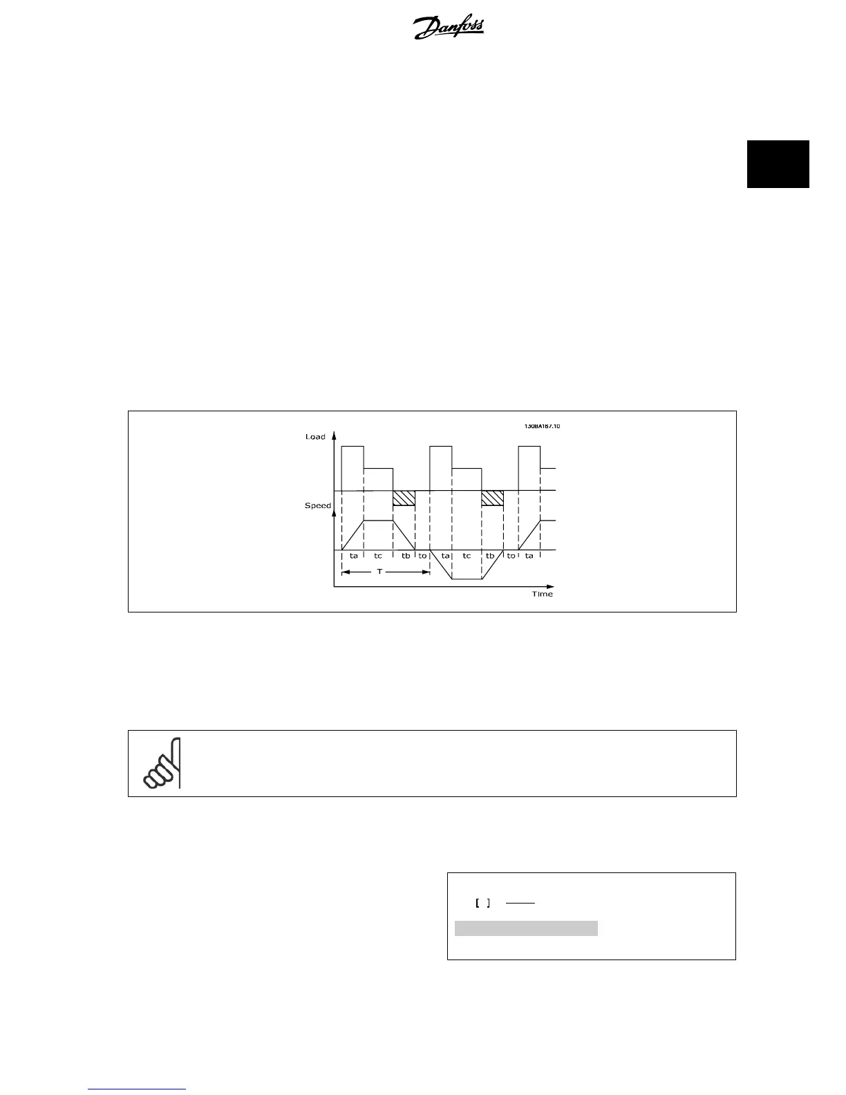
If the amount of kinetic energy transferred to the resistor in each braking period is not known, the average power can be calculated on the basis of the
cycle time and braking time also called intermitted duty cycle. The resistor intermittent duty cycle is an indication of the duty cycle at which the resistor
is active. The below figure shows a typical braking cycle.
The intermittent duty cycle for the resistor is calculated as follows:
Duty Cycle = t
b
/ T
T = cycle time in seconds
t
b
is the braking time in seconds (as part of the total cycle time)
Danfoss offers brake resistors with duty cycle of 5%, 10% and 40% suitable for use with the FC 102 frequency converter series. If a 10% duty cycle
resistor is applied, this is able of absorbing braking power upto 10% of the cycle time with the remaining 90% being used to dissipate heat from the
resistor.
For further selection advice, please contact Danfoss.
NB!
If a short circuit in the brake transistor occurs, power dissipation in the brake resistor is only prevented by using a mains switch or
contactor to disconnect the mains for the frequency converter. (The contactor can be controlled by the frequency converter).
2.12.2 Brake Resistor Calculation
The brake resistance is calculated as shown:
R
br
Ω =
U
dc
2
P
peak
where
P
peak
= P
motor
x M
br
x η
motor
x η[W]
VLT
®
HVAC Drive Design Guide 2 Introduction to VLT HVAC Drive
MG.11.B9.02 - VLT
®
is a registered Danfoss trademark
45
2

 Loading...


