• EN 61000-4-2 (IEC 61000-4-2): Electrostatic discharges (ESD): Simulation of electrostatic discharges from human beings.
• EN 61000-4-3 (IEC 61000-4-3): Incoming electromagnetic field radiation, amplitude modulated simulation of the effects of radar and radio
communication equipment as well as mobile communications equipment.
• EN 61000-4-4 (IEC 61000-4-4): Burst transients: Simulation of interference brought about by switching a contactor, relay or similar devices.
• EN 61000-4-5 (IEC 61000-4-5): Surge transients: Simulation of transients brought about e.g. by lightning that strikes near installations.
• EN 61000-4-6 (IEC 61000-4-6): RF Common mode: Simulation of the effect from radio-transmission equipment joined by connection cables.
See following EMC immunity form.
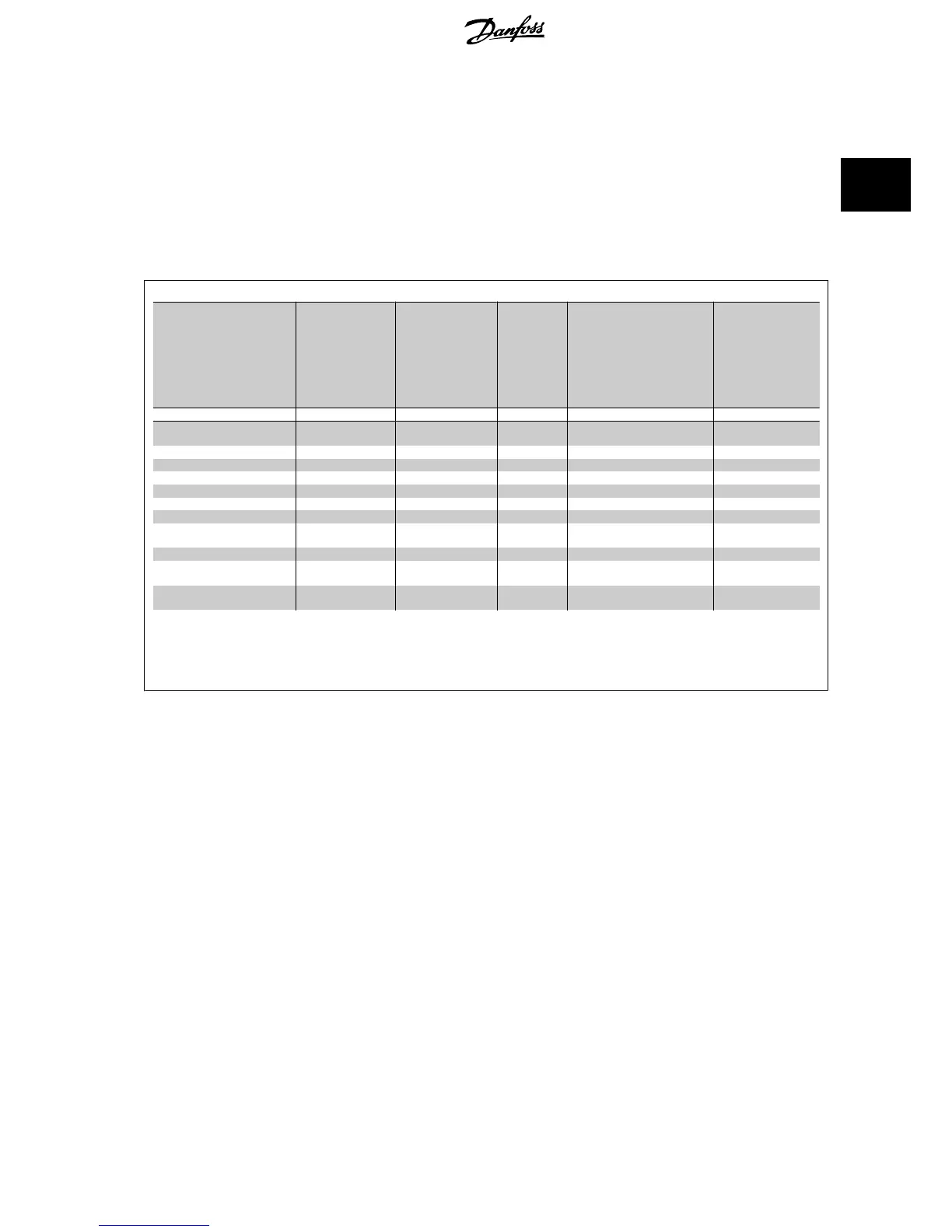
EMC immunity form
Voltage range: 200-240 V, 380-480 V
Basic standard Burst
IEC 61000-4-4
Surge
IEC 61000-4-5
ESD
IEC
61000-4-2
Radiated electromagnetic field
IEC 61000-4-3
RF common
mode voltage
IEC 61000-4-6
Acceptance criterion B B B A A
Line
4 kV CM
2 kV/2 Ω DM
4 kV/12 Ω CM
— —
10 V
RMS
Motor
4 kV CM
4 kV/2 Ω
1)
— —
10 V
RMS
Brake 4 kV CM
4 kV/2 Ω
1)
— —
10 V
RMS
Load sharing 4 kV CM
4 kV/2 Ω
1)
— —
10 V
RMS
Control wires
2 kV CM
2 kV/2 Ω
1)
— —
10 V
RMS
Standard bus 2 kV CM
2 kV/2 Ω
1)
— —
10 V
RMS
Relay wires 2 kV CM
2 kV/2 Ω
1)
— —
10 V
RMS
Application and Fieldbus op-
tions
2 kV CM
2 kV/2 Ω
1)
— —
10 V
RMS
LCP cable
2 kV CM
2 kV/2 Ω
1)
— —
10 V
RMS
External 24 V DC
2 kV CM
0.5 kV/2 Ω DM
1 kV/12 Ω CM
— —
10 V
RMS
Enclosure
— —
8 kV AD
6 kV CD
10 V/m —
AD: Air Discharge
CD: Contact Discharge
CM: Common mode
DM: Differential mode
1. Injection on cable shield.
Table 2.3: Immunity
2.10 Galvanic isolation (PELV)
2.10.1 PELV - Protective Extra Low Voltage
PELV offers protection by way of extra low voltage. Protection against electric shock is ensured when the electrical supply is of the PELV type and the
installation is made as described in local/national regulations on PELV supplies.
All control terminals and relay terminals 01-03/04-06 comply with PELV (Protective Extra Low Voltage) (Does not apply to grounded Delta leg above 400
V).
Galvanic (ensured) isolation is obtained by fulfilling requirements for higher isolation and by providing the relevant creapage/clearance distances. These
requirements are described in the EN 61800-5-1 standard.
The components that make up the electrical isolation, as described below, also comply with the requirements for higher isolation and the relevant test
as described in EN 61800-5-1.
The PELV galvanic isolation can be shown in six locations (see illustration):
In order to maintain PELV all connections made to the control terminals must be PELV, e.g. thermistor must be reinforced/double insulated.
VLT
®
HVAC Drive Design Guide 2 Introduction to VLT HVAC Drive
MG.11.B9.02 - VLT
®
is a registered Danfoss trademark
43
2

 Loading...


