7 RS-485 Installation and Set-up
7.1 RS-485 Installation and Set-up
7.1.1 Overview
RS-485 is a two-wire bus interface compatible with multi-drop network topology, i.e. nodes can be connected as a bus, or via drop cables from a common
trunk line. A total of 32 nodes can be connected to one network segment.
Network segments are divided up by repeaters. Please note that each repeater functions as a node within the segment in which it is installed. Each node
connected within a given network must have a unique node address, across all segments.
Terminate each segment at both ends, using either the termination switch (S801) of the frequency converters or a biased termination resistor network.
Always use screened twisted pair (STP) cable for bus cabling, and always follow good common installation practice.
Low-impedance ground connection of the screen at every node is very important, including at high frequencies. This can be achieved by connecting a
large surface of the screen to ground, for example by means of a cable clamp or a conductive cable gland. It may be necessary to apply potential-
equalizing cables to maintain the same ground potential throughout the network, particularly in installations where there are long lengths of cable.
To prevent impedance mismatch, always use the same type of cable throughout the entire network. When connecting a motor to the frequency converter,
always use screened motor cable.
Cable: Screened twisted pair (STP)
Impedance: 120 Ohm
Cable length: Max. 1200 m (including drop lines)
Max. 500 m station-to-station
7.1.2 Network connection
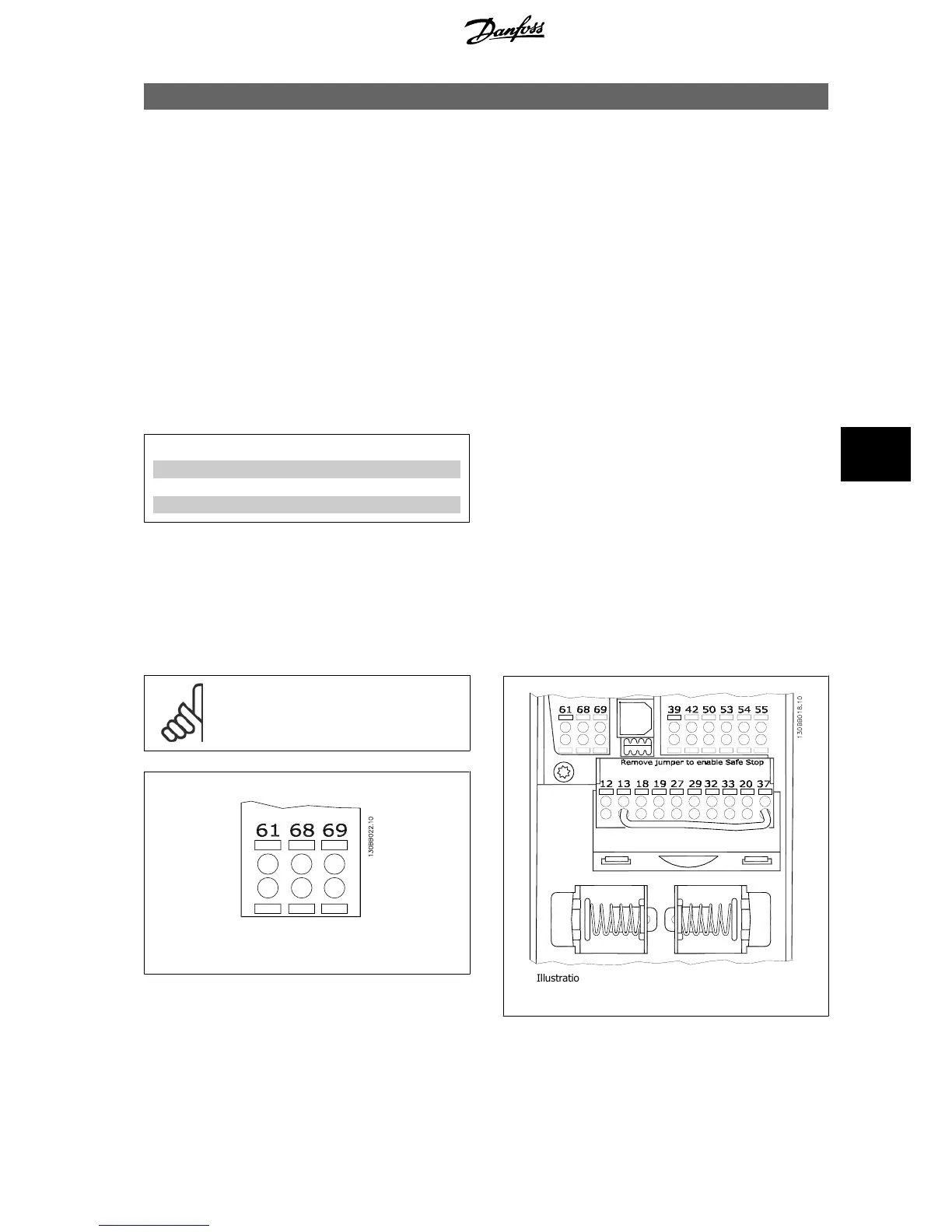
Connect the frequency converter to the RS-485 network as follows (see also diagram):
1. Connect signal wires to terminal 68 (P+) and terminal 69 (N-) on the main control board of the frequency converter.
2. Connect the cable screen to the cable clamps.
NB!
Screened, twisted-pair cables are recommended in or-
der to reduce noise between conductors.
Illustration 7.1: Network Terminal Connection

 Loading...


