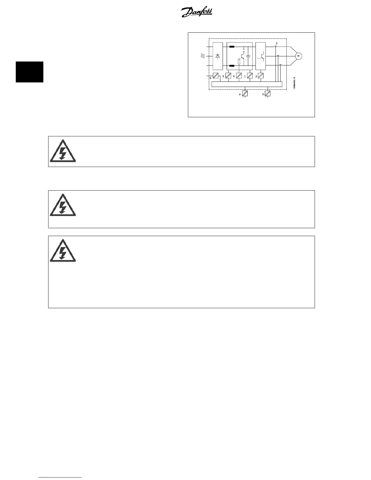
1. Power supply (SMPS) incl. signal isolation of U
DC
, indicating the
intermediate current voltage.
2. Gate drive that runs the IGBTs (trigger transformers/opto-cou-
plers).
3. Current transducers.
4. Opto-coupler, brake module.
5. Internal inrush, RFI, and temperature measurement circuits.
6. Custom relays.
Illustration 2.10: Galvanic isolation
The functional galvanic isolation (a and b on drawing) is for the 24 V back-up option and for the RS 485 standard bus interface.
Installation at high altitude:
380 - 500 V, enclosure A, B and C: At altitudes above 2 km, please contact Danfoss regarding PELV.
380 - 500V, enclosure D, E and F: At altitudes above 3 km, please contact Danfoss regarding PELV.
525 - 690 V: At altitudes above 2 km, please contact Danfoss regarding PELV.
2.11 Earth Leakage Current
Touching the electrical parts may be fatal - even after the equipment has been disconnected from mains.
Also make sure that other voltage inputs have been disconnected, such as load sharing (linkage of DC intermediate circuit), as well as
the motor connection for kinetic back-up.
Before touching any electrical parts, wait at least the amount of time indicated in the
Safety Precautions
section.
Shorter time is allowed only if indicated on the nameplate for the specific unit.
Leakage Current
The earth leakage current from the frequency converter exceeds 3.5 mA. To ensure that the earth cable has a good mechanical
connection to the earth connection (terminal 95), the cable cross section must be at least 10 mm
2
or 2 rated earth wires terminated
separately.
Residual Current Device
This product can cause a d.c. current in the protective conductor. Where a residual current device (RCD) is used for protection in case
of direct or indirect contact, only an RCD of Type B is allowed on the supply side of this product. Otherwise, another protective measure
shall be applied, such as separation from the environment by double or reinforced insulation, or isolation from the supply system by a
transformer. See also RCD Application Note MN.90.GX.02.
Protective earthing of the frequency converter and the use of RCD's must always follow national and local regulations.
2 Introduction to VLT HVAC Drive VLT
®
HVAC Drive Design Guide
44
MG.11.B9.02 - VLT
®
is a registered Danfoss trademark
2

 Loading...


