• When all relays are de-energized, the first built in relay to be energized will cut in the contactor corresponding to the pump controlled by the
relay. E.g. RELAY 1 cuts in contactor K1, which becomes the lead pump.
• K1 blocks for K2 via the mechanical interlock preventing mains to be connected to the output of the frequency converter (via K1).
• Auxiliary break contact on K1 prevents K3 to cut in.
• RELAY 2 controls contactor K4 for on/off control of the fixed speed pump.
• At alternation both relays de-energizes and now RELAY 2 will be energized as the first relay.
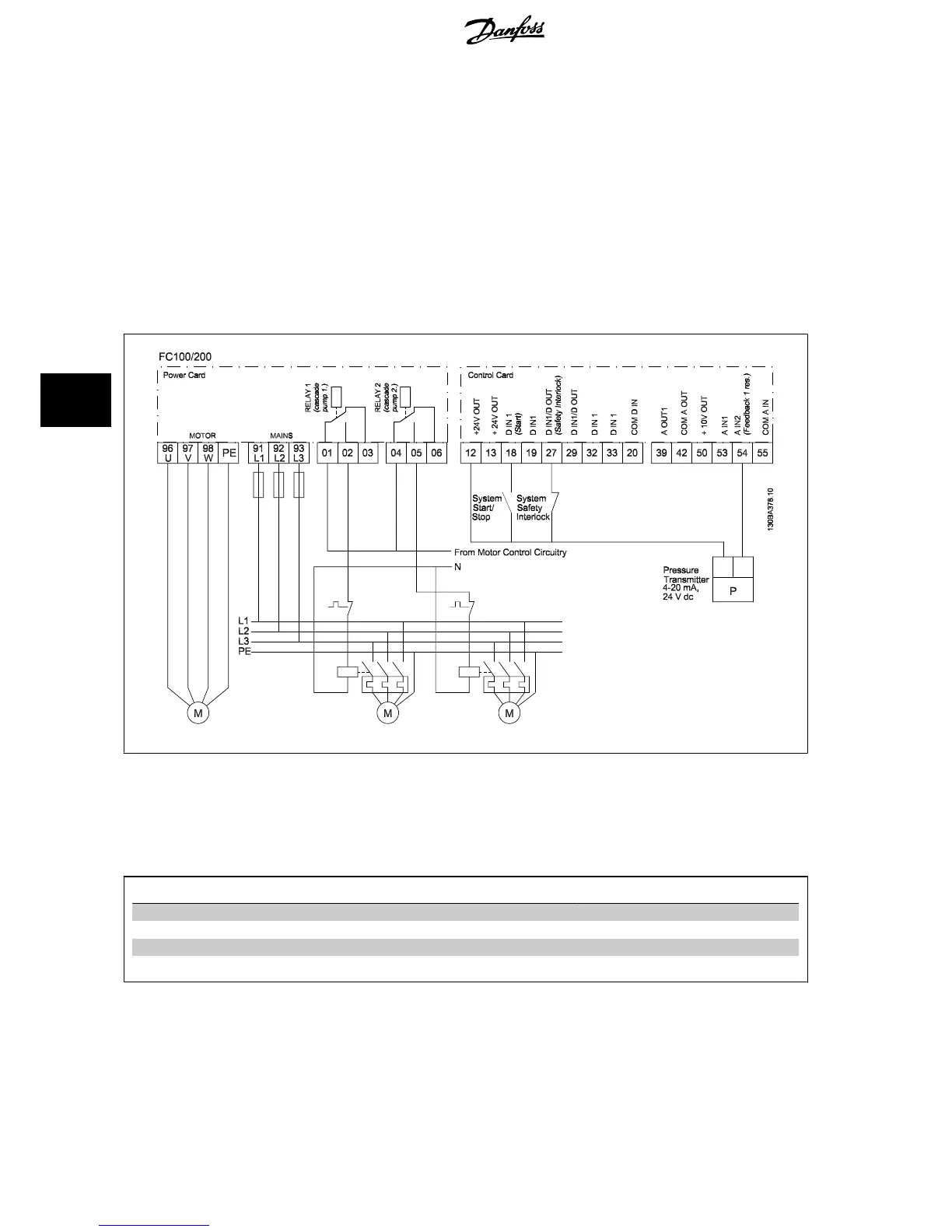
6.1.13 Cascade Controller Wiring Diagram
The wiring diagram shows an example with the built in BASIC cascade controller with one variable speed pump (lead) and two fixed speed pumps, a
4-20 mA transmitter and System Safety Interlock.
6.1.14 Start/Stop conditions
Commands assigned to digital inputs. See
Digital Inputs
, parameter group 5-1*.
Variable speed pump (lead) Fixed speed pumps
Start (SYSTEM START /STOP) Ramps up (if stopped and there is a demand) Staging (if stopped and there is a demand)
Lead Pump Start Ramps up if SYSTEM START is active Not affected
Coast (EMERGENCY STOP) Coast to stop Cut out (built in relays are de-energized)
Safety Interlock Coast to stop Cut out (built in relays are de-energized)
Function of buttons on LCP:
6 Application Examples VLT
®
HVAC Drive Design Guide
126
MG.11.B9.02 - VLT
®
is a registered Danfoss trademark
6

 Loading...


