7.7 Network Configuration
To enable Modbus RTU on the frequency converter, set the following parameters:
Parameter Number
Parameter name Setting
8-30 Protocol Modbus RTU
8-31 Address 1 - 247
8-32 Baud Rate 2400 - 115200
8-33 Parity/Stop bits Even parity, 1 stop bit (default)
7.8 Modbus RTU Message Framing Structure
7.8.1 Frequency Converter with Modbus RTU
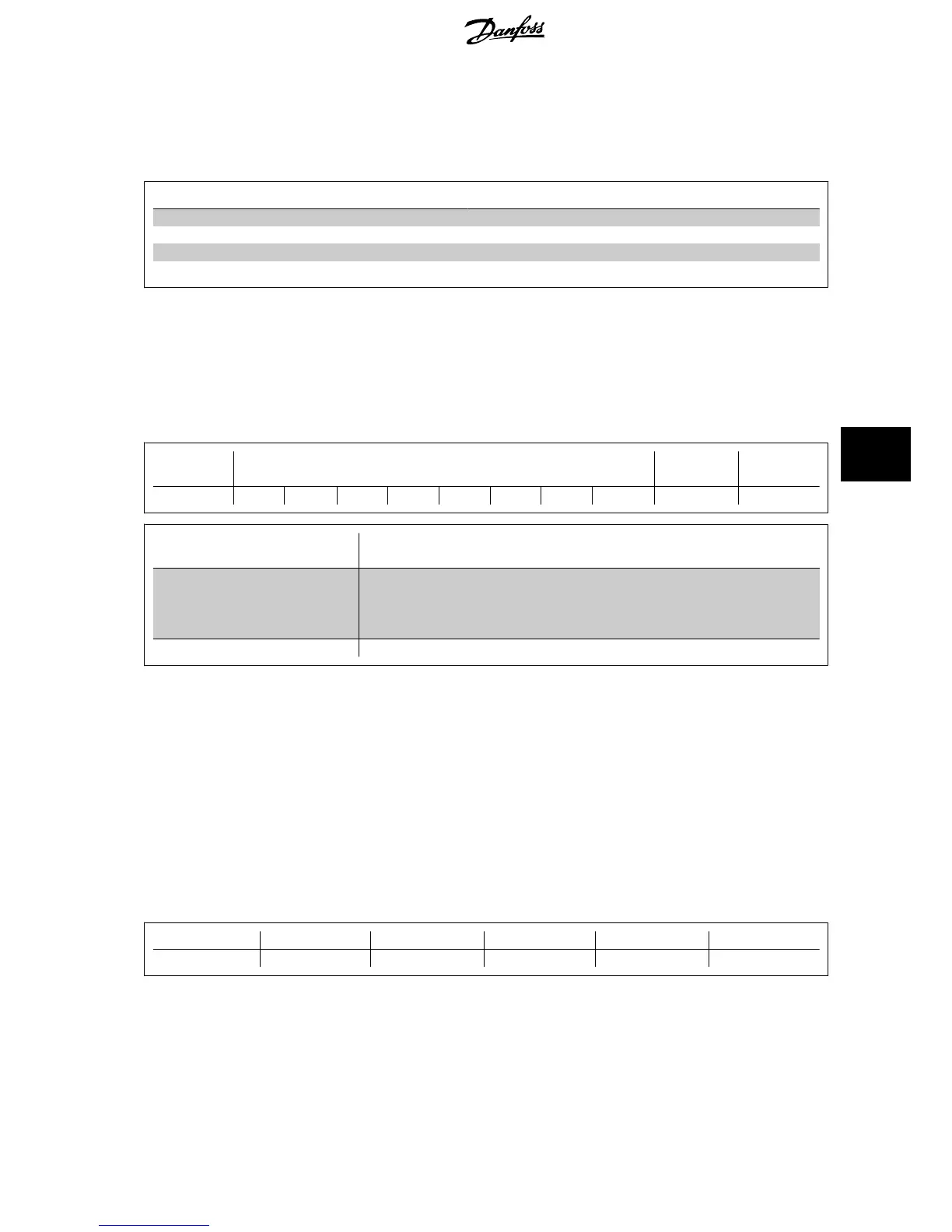
The controllers are set up to communicate on the Modbus network using RTU (Remote Terminal Unit) mode, with each byte in a message containing two
4-bit hexadecimal characters. The format for each byte is shown below.
Start bit
Data byte Stop/
parity
Stop
Coding System 8-bit binary, hexadecimal 0-9, A-F. Two hexadecimal characters contained in each 8-bit field of the
message
Bits Per Byte 1 start bit
8 data bits, least significant bit sent first
1 bit for even/odd parity; no bit for no parity
1 stop bit if parity is used; 2 bits if no parity
Error Check Field Cyclical Redundancy Check (CRC)
7.8.2 Modbus RTU Message Structure
The transmitting device places a Modbus RTU message into a frame with a known beginning and ending point. This allows receiving devices to begin at
the start of the message, read the address portion, determine which device is addressed (or all devices, if the message is broadcast), and to recognise
when the message is completed. Partial messages are detected and errors set as a result. Characters for transmission must be in hexadecimal 00 to FF
format in each field. The frequency converter continuously monitors the network bus, also during ‘silent’ intervals. When the first field (the address field)
is received, each frequency converter or device decodes it to determine which device is being addressed. Modbus RTU messages addressed to zero are
broadcast messages. No response is permitted for broadcast messages. A typical message frame is shown below.
Typical Modbus RTU Message Structure
Start
Address Function Data CRC check End
T1-T2-T3-T4 8 bits 8 bits N x 8 bits 16 bits T1-T2-T3-T4
7.8.3 Start / Stop Field
Messages start with a silent period of at least 3.5 character intervals. This is implemented as a multiple of character intervals at the selected network
baud rate (shown as Start T1-T2-T3-T4). The first field to be transmitted is the device address. Following the last transmitted character, a similar period
of at least 3.5 character intervals marks the end of the message. A new message can begin after this period. The entire message frame must be transmitted
VLT
®
HVAC Drive Design Guide 7 RS-485 Installation and Set-up
MG.11.B9.02 - VLT
®
is a registered Danfoss trademark
139
7

 Loading...


