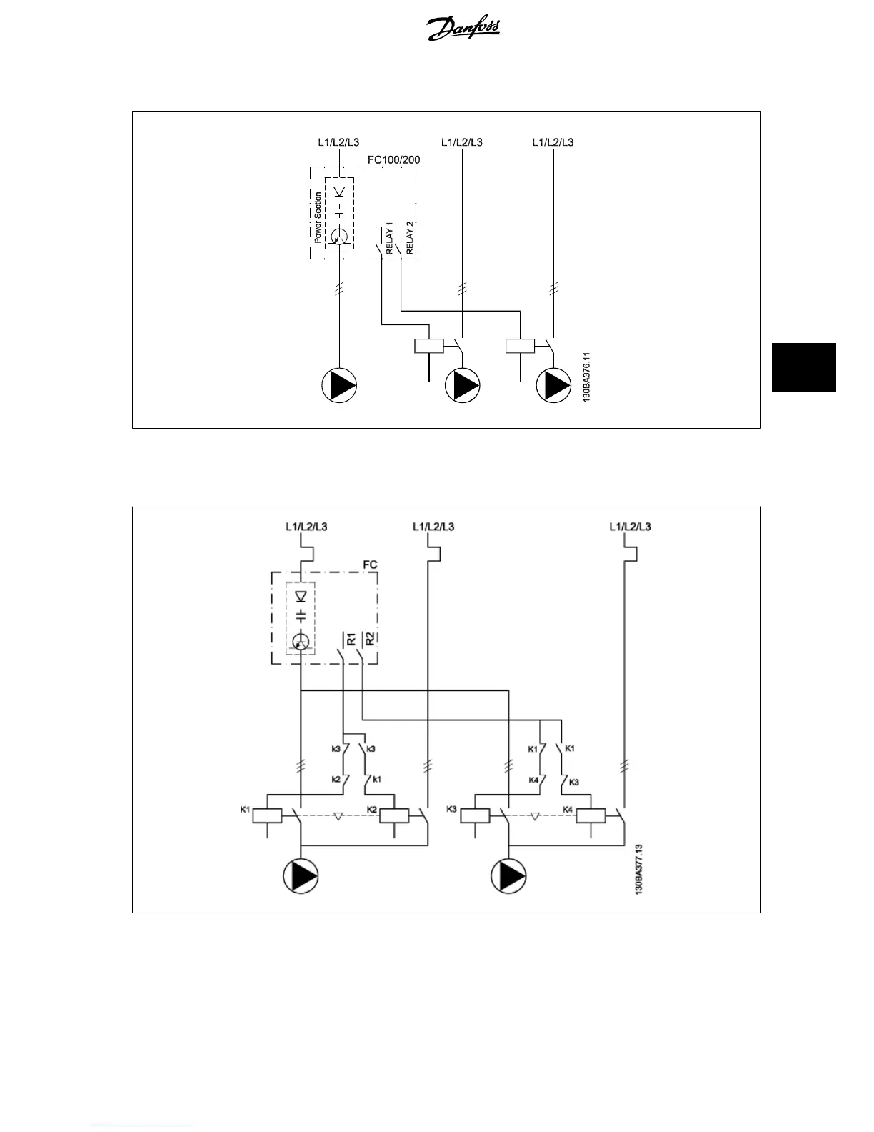
6.1.11 Fixed Variable Speed Pump Wiring Diagram
6.1.12 Lead Pump Alternation Wiring Diagram
Every pump must be connected to two contactors (K1/K2 and K3/K4) with a mechanical interlock. Thermal relays or other motor protection devices must
be applied according to local regulation and/or individual demands.
• RELAY 1 (R1) and RELAY 2 (R2) are the built-in relays in the frequency converter.
VLT
®
HVAC Drive Design Guide 6 Application Examples
MG.11.B9.02 - VLT
®
is a registered Danfoss trademark
125
6

 Loading...


