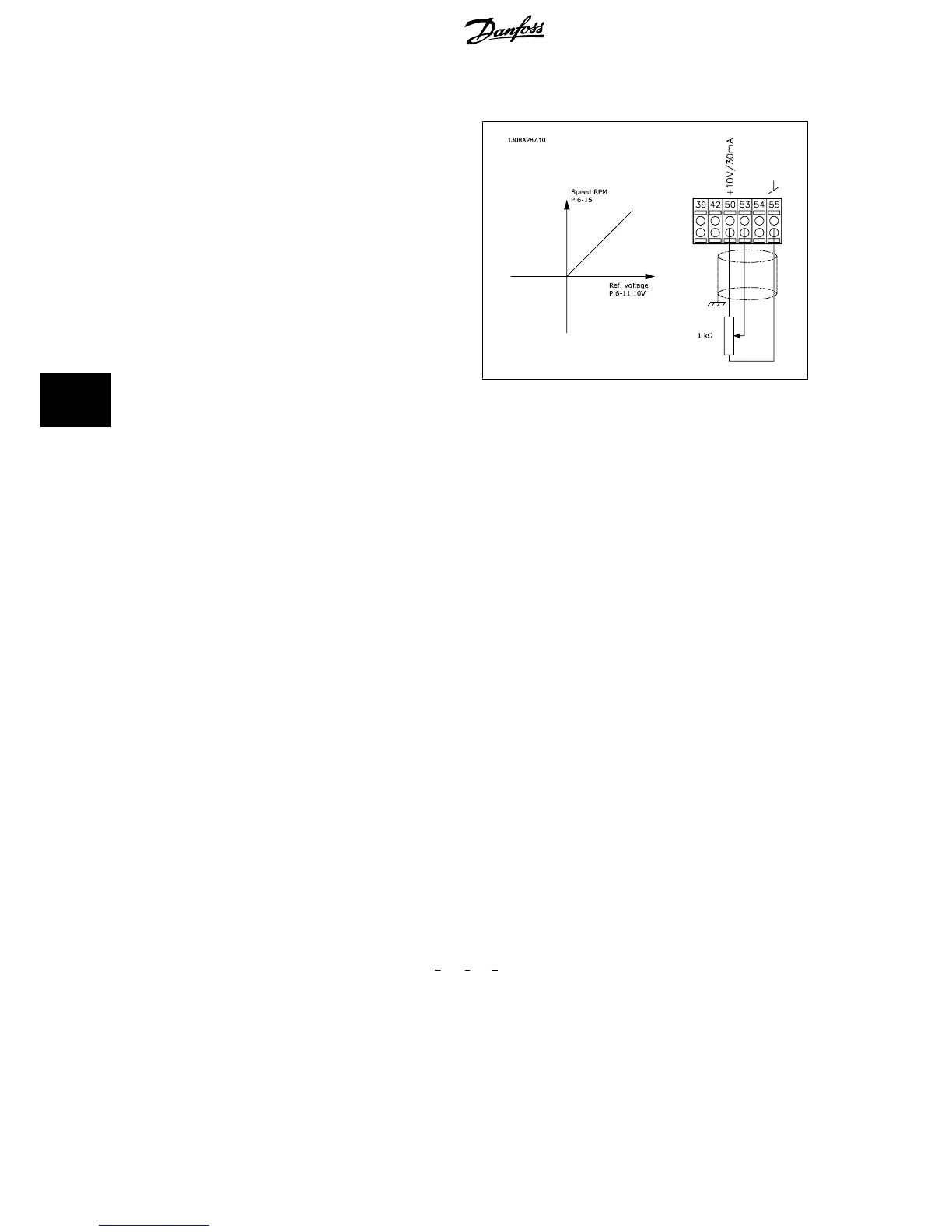
6.1.3 Potentiometer Reference
Voltage reference via a potentiometer.
Par. 3-15
Reference 1 Source
[1] =
Analog Input 53
Par. 6-10
Terminal 53 Low Voltage
= 0 Volt
Par. 6-11
Terminal 53 High Voltage
= 10 Volt
Par. 6-14
Terminal 53 Low Ref./Feedb. Value
= 0 RPM
Par. 6-15
Terminal 53 High Ref./Feedb. Value
= 1.500 RPM
Switch S201 = OFF (U)
6.1.4 Automatic Motor Adaptation (AMA)
AMA is an algorithm to measure the electrical motor parameters on a motor at standstill. This means that AMA itself does not supply any torque.
AMA is useful when commissioning systems and optimising the adjustment of the frequency converter to the applied motor. This feature is particularly
used where the default setting does not apply to the connected motor.
Par. 1-29
Automatic Motor Adaptation (AMA)
allows a choice of complete AMA with determination of all electrical motor parameters or reduced AMA with
determination of the stator resistance Rs only.
The duration of a total AMA varies from a few minutes on small motors to more than 15 minutes on large motors.
Limitations and preconditions:
• For the AMA to determine the motor parameters optimally, enter the correct motor nameplate data in par. 1-20
Motor Power [kW]
to
par. 1-28
Motor Rotation Check
.
• For the best adjustment of the frequency converter, carry out AMA on a cold motor. Repeated AMA runs may lead to a heating of the motor,
which results in an increase of the stator resistance, Rs. Normally, this is not critical.
• AMA can only be carried out if the rated motor current is minimum 35% of the rated output current of the frequency converter. AMA can be
carried out on up to one oversize motor.
• It is possible to carry out a reduced AMA test with a Sine-wave filter installed. Avoid carrying out a complete AMA with a Sine-wave filter. If an
overall setting is required, remove the Sine-wave filter while running a total AMA. After completion of the AMA, reinsert the Sine-wave filter.
• If motors are coupled in parallel, use only reduced AMA if any.
• Avoid running a complete AMA when using synchronous motors. If synchronous motors are applied, run a reduced AMA and manually set the
extended motor data. The AMA function does not apply to permanent magnet motors.
• The frequency converter does not produce motor torque during an AMA. During an AMA, it is imperative that the application does not force the
motor shaft to run, which is known to happen with e.g. wind milling in ventilation systems. This disturbs the AMA function.
6.1.5 Smart Logic Control
New useful facility in the VLT HVAC Drive frequency converter is the Smart Logic Control (SLC).
In applications where a PLC is generating a simple sequence the SLC may take over elementary tasks from the main control.
SLC is designed to act from event send to or generated in the frequency converter. The frequency converter will then perform the pre-programmed
action.
6 Application Examples VLT
®
HVAC Drive Design Guide
120
MG.11.B9.02 - VLT
®
is a registered Danfoss trademark
6

 Loading...


