5.7.3 Earthing of Screened/Armoured Control Cables
Generally speaking, control cables must be braided screened/armoured and the screen must be connected by means of a cable clamp at both ends to
the metal cabinet of the unit.
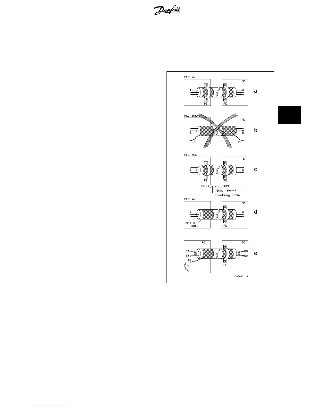
The drawing below indicates how correct earthing is carried out and what to do if in doubt.
a. Correct earthing
Control cables and cables for serial communication must be fit-
ted with cable clamps at both ends to ensure the best possible
electrical contact.
b. Wrong earthing
Do not use twisted cable ends (pigtails). They increase the
screen impedance at high frequencies.
c. Protection with respect to earth potential between PLC
and frequency converter
If the earth potential between the frequency converter and the
PLC (etc.) is different, electric noise may occur that will disturb
the entire system. Solve this problem by fitting an equalising
cable, next to the control cable. Minimum cable cross-section:
16 mm
2
.
d. For 50/60 Hz earth loops
If very long control cables are used, 50/60 Hz earth loops may
occur. Solve this problem by connecting one end of the screen
to earth via a 100nF capacitor (keeping leads short).
e. Cables for serial communication
Eliminate low-frequency noise currents between two frequency
converters by connecting one end of the screen to terminal 61.
This terminal is connected to earth via an internal RC link. Use
twisted-pair cables to reduce the differential mode interference
between the conductors.
5.8.1 Residual Current Device
You can use RCD relays, multiple protective earthing or earthing as extra protection, provided that local safety regulations are complied with.
If an earth fault appears, a DC content may develop in the faulty current.
If RCD relays are used, you must observe local regulations. Relays must be suitable for protection of 3-phase equipment with a bridge rectifier and for
a brief discharge on power-up see section
Earth Leakage Current
for further information.
VLT
®
HVAC Drive Design Guide 5 How to Install
MG.11.B9.02 - VLT
®
is a registered Danfoss trademark
117
5

 Loading...


