7.2 FC Protocol Overview
The FC protocol, also referred to as FC bus or Standard bus, is the Danfoss standard fieldbus. It defines an access technique according to the master-
slave principle for communications via a serial bus.
One master and a maximum of 126 slaves can be connected to the bus. The individual slaves are selected by the master via an address character in the
telegram. A slave itself can never transmit without first being requested to do so, and direct message transfer between the individual slaves is not possible.
Communications occur in the half-duplex mode.
The master function cannot be transferred to another node (single-master system).
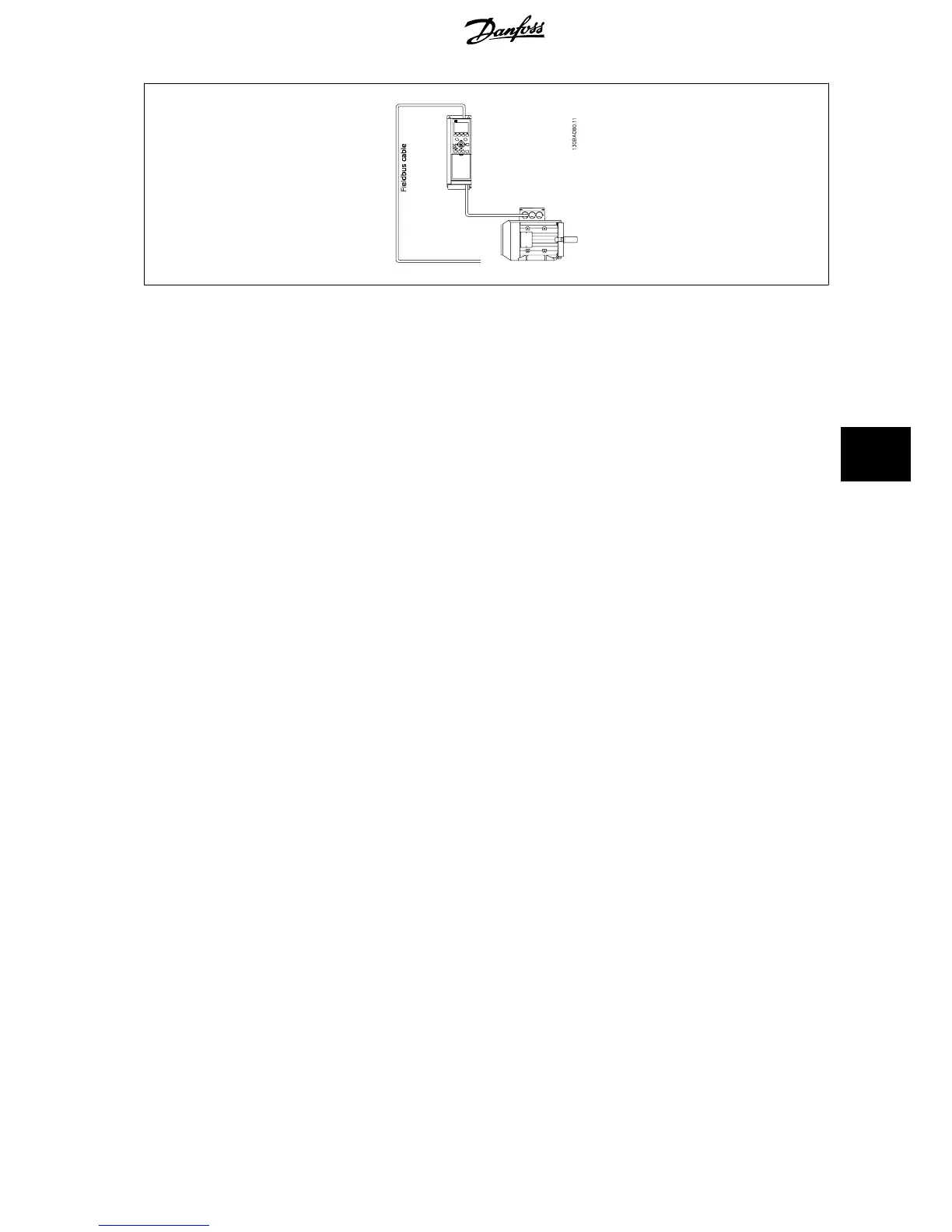
The physical layer is RS-485, thus utilizing the RS-485 port built into the frequency converter. The FC protocol supports different telegram formats; a
short format of 8 bytes for process data, and a long format of 16 bytes that also includes a parameter channel. A third telegram format is used for texts.
7.2.1 FC with Modbus RTU
The FC protocol provides access to the Control Word and Bus Reference of the frequency converter.
The Control Word allows the Modbus master to control several important functions of the frequency converter:
•Start
• Stop of the frequency converter in various ways:
Coast stop
Quick stop
DC Brake stop
Normal (ramp) stop
• Reset after a fault trip
• Run at a variety of preset speeds
• Run in reverse
• Change of the active set-up
• Control of the two relays built into the frequency converter
The Bus Reference is commonly used for speed control. It is also possible to access the parameters, read their values, and where possible, write values
to them. This permits a range of control options, including controlling the setpoint of the frequency converter when its internal PID controller is used.
7.3 Network Configuration
7.3.1 Frequency Converter Set-up
Set the following parameters to enable the FC protocol for the frequency converter.
VLT
®
HVAC Drive Design Guide 7 RS-485 Installation and Set-up
MG.11.B9.02 - VLT
®
is a registered Danfoss trademark
131
7

 Loading...


