7.1.3 Frequency converter hardware setup
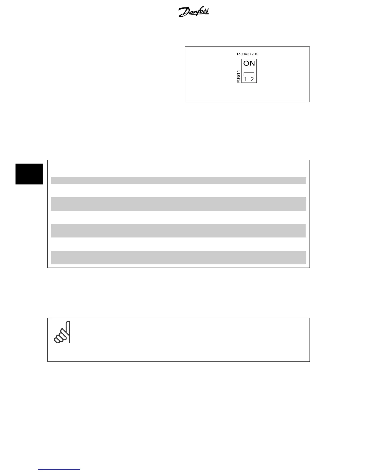
Use the terminator dip switch on the main control board of the frequency
converter to terminate the RS-485 bus.
Illustration 7.3: Terminator Switch Factory Setting
The factory setting for the dip switch is OFF.
7.1.4 Frequency Converter Parameter Settings for Modbus Communication
The following parameters apply to the RS-485 interface (FC-port):
Parameter
Number
Parameter name Function
8-30 Protocol Select the application protocol to run on the RS-485 interface
8-31 Address Set the node address. Note: The address range depends on the protocol se-
lected in par. 8-30
Protocol
8-32 Baud Rate Set the baud rate. Note: The default baud rate depends on the protocol se-
lected in par. 8-30
Protocol
8-33 PC port parity/Stop bits Set the parity and number of stop bits. Note: The default selection depends
on the protocol selected in par. 8-30
Protocol
8-35 Min. response delay Specify a minimum delay time between receiving a request and transmitting
a response. This can be used for overcoming modem turnaround delays.
8-36 Max. response delay Specify a maximum delay time between transmitting a request and receiving
a response.
8-37 Max. inter-char delay Specify a maximum delay time between two received bytes to ensure time-
out if transmission is interrupted.
7.1.5 EMC Precautions
The following EMC precautions are recommended in order to achieve interference-free operation of the RS-485 network.
NB!
Relevant national and local regulations, for example regarding protective earth connection, must be observed. The RS-485 communi-
cation cable must be kept away from motor and brake resistor cables to avoid coupling of high frequency noise from one cable to
another. Normally a distance of 200 mm (8 inches) is sufficient, but keeping the greatest possible distance between the cables is
generally recommended, especially where cables run in parallel over long distances. When crossing is unavoidable, the RS-485 cable
must cross motor and brake resistor cables at an angle of 90 degrees.
7 RS-485 Installation and Set-up VLT
®
HVAC Drive Design Guide
130
MG.11.B9.02 - VLT
®
is a registered Danfoss trademark
7

 Loading...


