5.2.2 Electrical installation and control cables
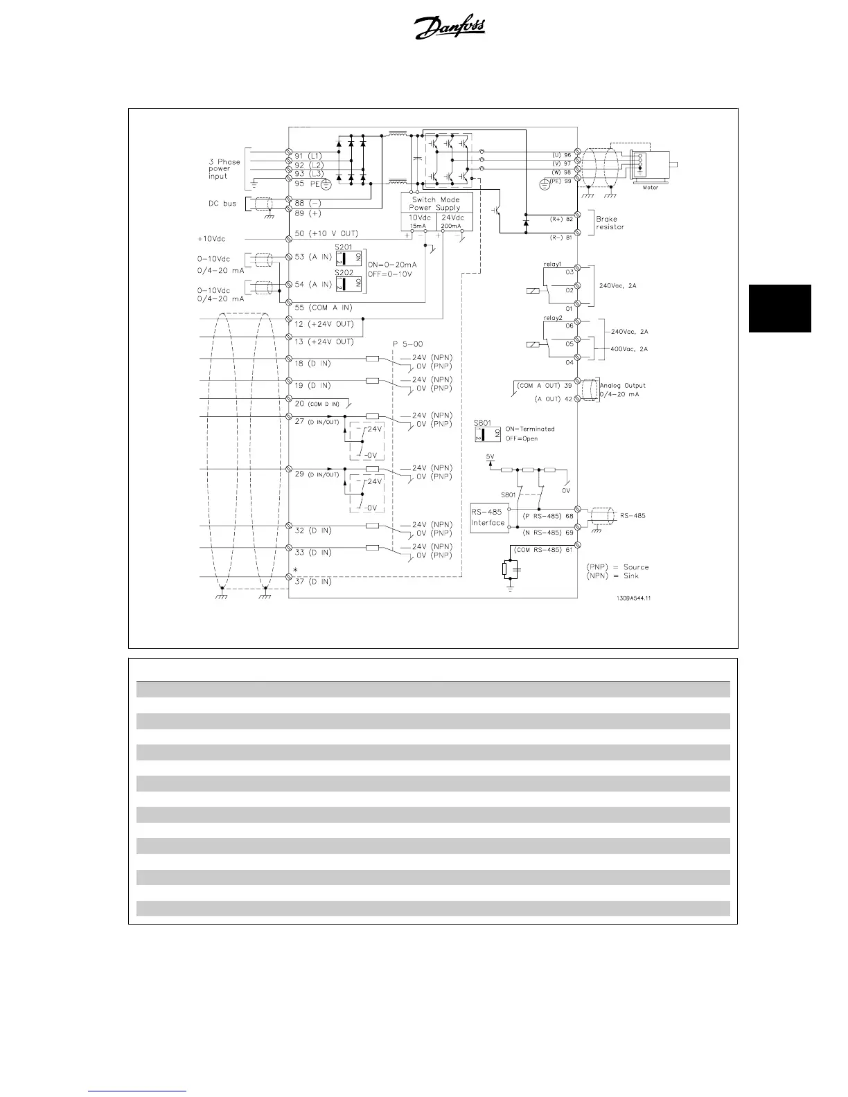
Illustration 5.8: Diagram showing all electrical terminals. (Terminal 37 present for units with Safe Stop Function only.)
Terminal number Terminal description Parameter number Factory default
1+2+3 Terminal 1+2+3-Relay1 5-40 No operation
4+5+6 Terminal 4+5+6-Relay2 5-40 No operation
12 Terminal 12 Supply - +24 V DC
13 Terminal 13 Supply - +24 V DC
18 Terminal 18 Digital Input 5-10 Start
19 Terminal 19 Digital Input 5-11 No operation
20 Terminal 20 - Common
27 Terminal 27 Digital Input/Output 5-12/5-30 Coast inverse
29 Terminal 29 Digital Input/Output 5-13/5-31 Jog
32 Terminal 32 Digital Input 5-14 No operation
33 Terminal 33 Digital Input 5-15 No operation
37 Terminal 37 Digital Input - Safe Stop
42 Terminal 42 Analog Output 6-50 Speed 0-HighLim
53 Terminal 53 Analog Input 3-15/6-1*/20-0* Reference
54 Terminal 54 Analog Input 3-15/6-2*/20-0* Feedback
Table 5.3: Terminal connections
VLT
®
HVAC Drive Design Guide 5 How to Install
MG.11.B9.02 - VLT
®
is a registered Danfoss trademark
89
5

 Loading...


