6 Application Examples
6.1.1 Start/Stop
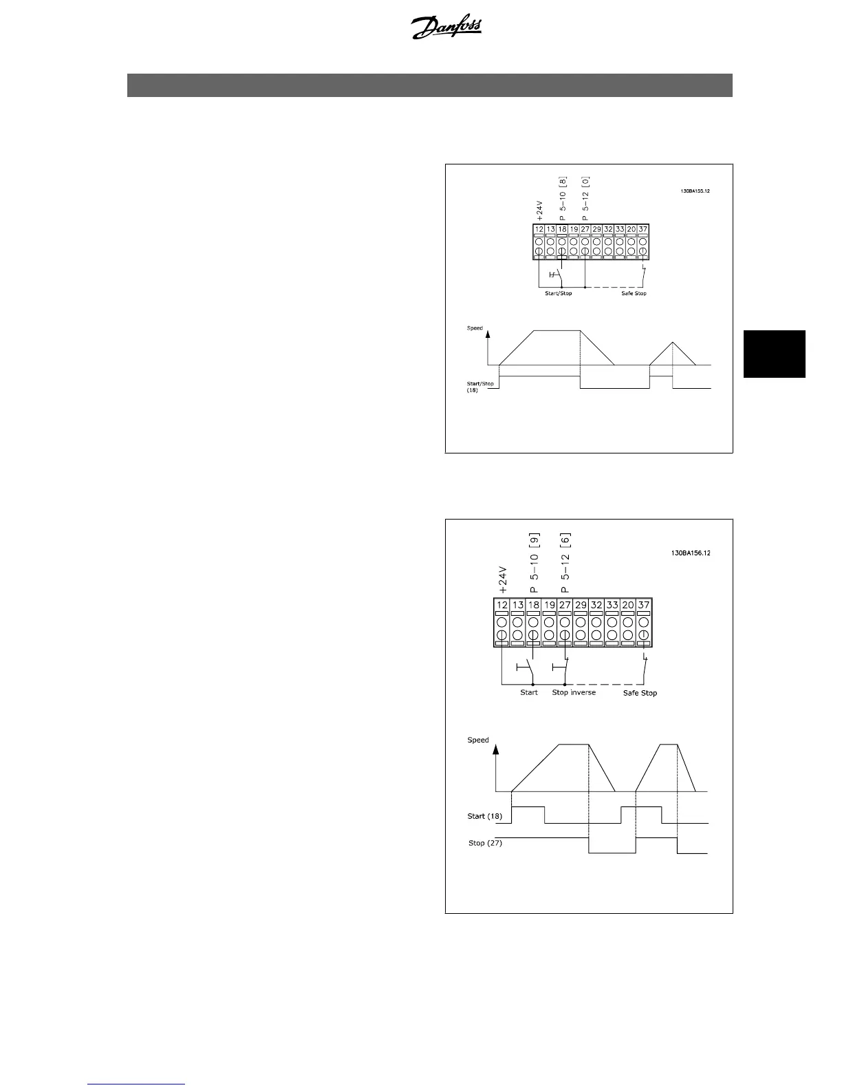
Terminal 18 = start/stop par. 5-10
Terminal 18 Digital Input
[8]
Start
Terminal 27 = No operation par. 5-12
Terminal 27 Digital Input
[0]
No
operation
(Default
coast inverse
Par. 5-10
Terminal 18 Digital Input
=
Start
(default)
Par. 5-12
Terminal 27 Digital Input
=
coast inverse
(default)
Illustration 6.1: Terminal 37: Available only with Safe Stop
Function!
6.1.2 Pulse Start/Stop
Terminal 18 = start/stop par. 5-10
Terminal 18 Digital Input
[9]
Latched
start
Terminal 27= Stop par. 5-12
Terminal 27 Digital Input
[6]
Stop inverse
Par. 5-10
Terminal 18 Digital Input
=
Latched start
Par. 5-12
Terminal 27 Digital Input
=
Stop inverse
Illustration 6.2: Terminal 37: Available only with Safe Stop
Function!
VLT
®
HVAC Drive Design Guide 6 Application Examples
MG.11.B9.02 - VLT
®
is a registered Danfoss trademark
119
6

 Loading...


