As can be seen, the brake resistance depends on the intermediate circuit voltage (U
DC
).
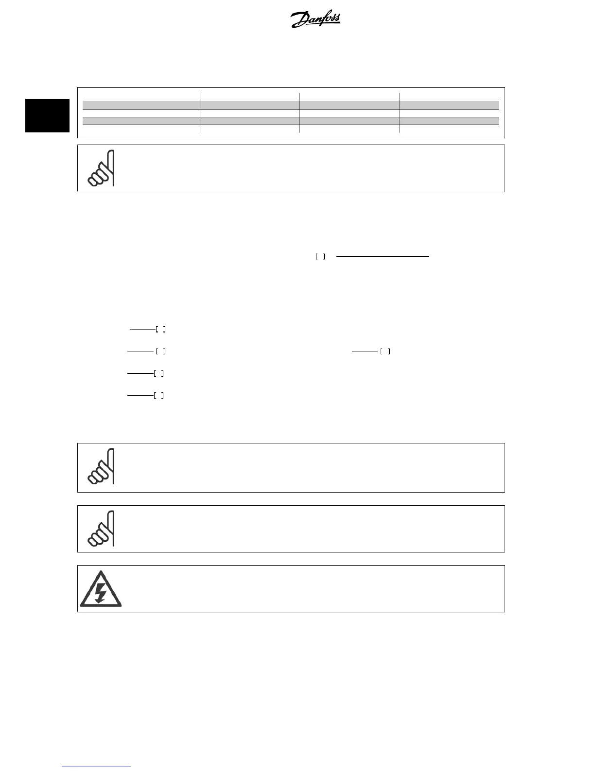
The brake function of the frequency converter is settled in 3 areas of mains power supply:
Size
Brake active Warning before cut out Cut out (trip)
3 x 200-240 V 390 V (U
DC
) 405 V 410 V
3 x 380-480 V 778 V 810 V 820 V
3 x 525-600 V 943 V 965 V 975 V
3 x 525-690 V 1084 V 1109 V 1130 V
NB!
Check that the brake resistor can cope with a voltage of 410 V, 820 V or 975 V - unless Danfoss brake resistors are used.
Danfoss recommends the brake resistance R
rec
, i.e. one that guarantees that the frequency converter is able to brake at the highest braking torque
(M
br(%)
) of 110%. The formula can be written as:
R
rec
Ω =
U
dc
2
x
100
P
motor
x
M
br
(%)
x
x
motor
η
motor
is typically at 0.90 η is typically at 0.98
For 200 V, 480 V and 600 V frequency converters, R
rec
at 160% braking torque is written as:
200
V
:
R
rec
=
107780
P
motor
Ω
480
V
:
R
rec
=
375300
P
motor
Ω
1)
480
V
:
R
rec
=
428914
P
motor
Ω
2)
600
V
:
R
rec
=
630137
P
motor
Ω
690
V
:
R
rec
=
832664
P
motor
Ω
1) For frequency converters ≤ 7.5 kW shaft output
2) For frequency converters > 7.5 kW shaft output
NB!
The resistor brake circuit resistance selected should not be higher than that recommended by Danfoss. If a brake resistor with a higher
ohmic value is selected, the braking torque may not be achieved because there is a risk that the frequency converter cuts out for safety
reasons.
NB!
If a short circuit in the brake transistor occurs, power dissipation in the brake resistor is only prevented by using a mains switch or
contactor to disconnect the mains for the frequency converter. (The contactor can be controlled by the frequency converter).
Do not touch the brake resistor as it can get very hot while/after braking.
2 Introduction to VLT HVAC Drive VLT
®
HVAC Drive Design Guide
46
MG.11.B9.02 - VLT
®
is a registered Danfoss trademark
2

 Loading...


