Bit 13/14, Selection of set-up:
Use bits 13 and 14 to choose from the four menu set-ups according to
the shown table: .
Set-up
Bit 14 Bit 13
1 0 0
201
3 1 0
411
The function is only possible when
Multi Set-Ups
is selected in
par. 0-10
Active Set-up
.
Make a selection in par. 8-55
Set-up Select
to define how Bit 13/14 gates
with the corresponding function on the digital inputs.
Bit 15 Reverse:
Bit 15 = ’0’: No reversing. Bit 15 = ’1’: Reversing. In the default setting, reversing is set to digital in par. 8-54
Reversing Select
. Bit 15 causes reversing
only when Ser. communication, Logic or or Logic and is selected.
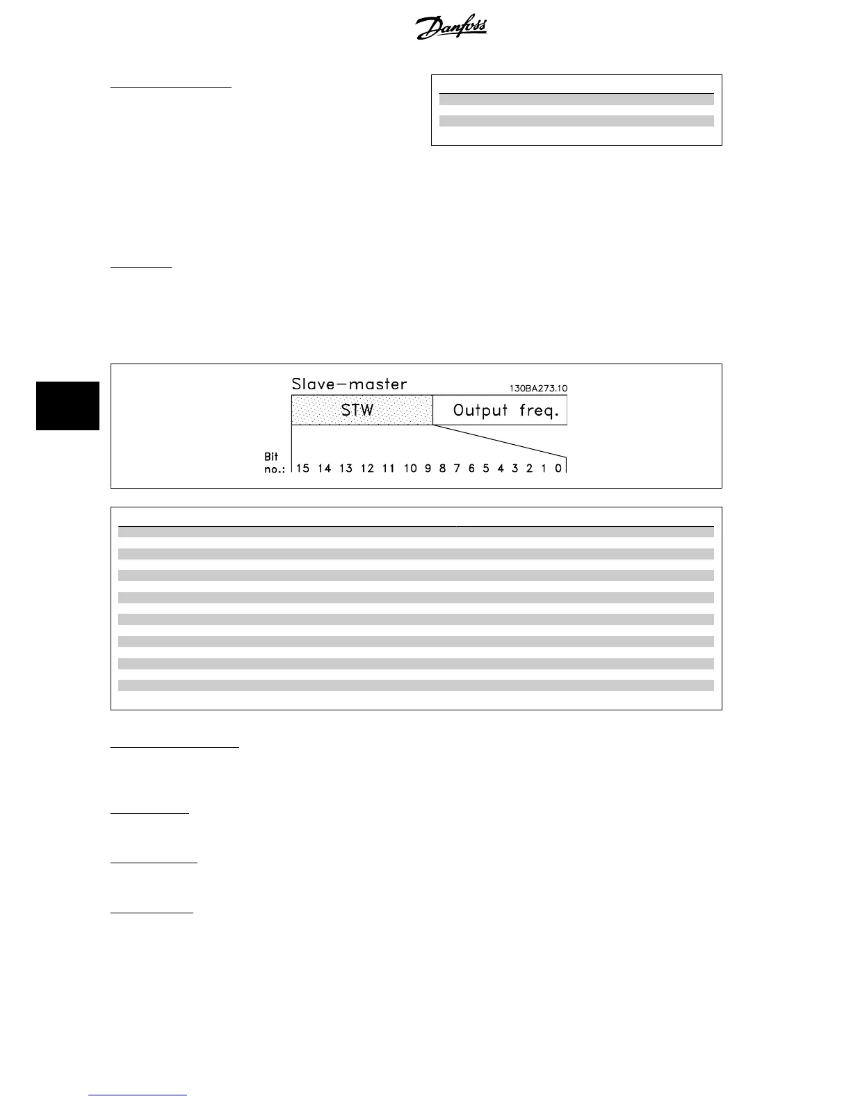
7.11.2 Status Word According to FC Profile (STW) (par. 8-10
Control Profile
= FC profile)
Bit Bit = 0 Bit = 1
00 Control not ready Control ready
01 Drive not ready Drive ready
02 Coasting Enable
03 No error Trip
04 No error Error (no trip)
05 Reserved -
06 No error Triplock
07 No warning Warning
08 Speed ≠ reference Speed = reference
09 Local operation Bus control
10 Out of frequency limit Frequency limit OK
11 No operation In operation
12 Drive OK Stopped, auto start
13 Voltage OK Voltage exceeded
14 Torque OK Torque exceeded
15 Timer OK Timer exceeded
Explanation of the Status Bits
Bit 00, Control not ready/ready:
Bit 00 = ’0’: The frequency converter trips. Bit 00 = ’1’: The frequency converter controls are ready but the power component does not necessarily receive
any power supply (in case of external 24 V supply to controls).
Bit 01, Drive ready:
Bit 01 = ’1’: The frequency converter is ready for operation but the coasting command is active via the digital inputs or via serial communication.
Bit 02, Coasting stop:
Bit 02 = ’0’: The frequency converter releases the motor. Bit 02 = ’1’: The frequency converter starts the motor with a start command.
Bit 03, No error/trip:
Bit 03 = ’0’ : The frequency converter is not in fault mode. Bit 03 = ’1’: The frequency converter trips. To re-establish operation, enter [Reset].
7 RS-485 Installation and Set-up VLT
®
HVAC Drive Design Guide
152
MG.11.B9.02 - VLT
®
is a registered Danfoss trademark
7

 Loading...


