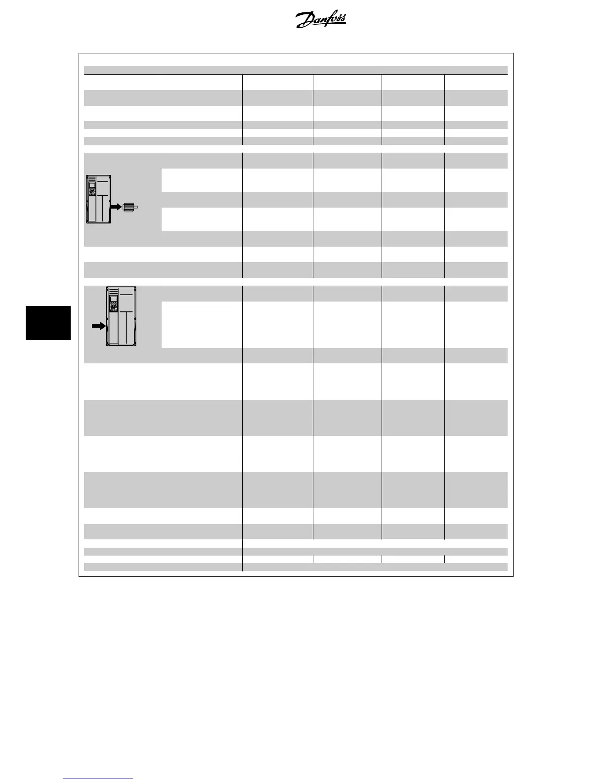
Mains Supply 3 x 525- 690 VAC
P132 P160 P200 P250
Typical Shaft output at 550
V [kW]
110 132 160 200
Typical Shaft output at 575
V [HP]
150 200 250 300
Typical Shaft output at 690
V [kW]
132 160 200 250
Enclosure IP21 D1 D1 D2 D2
Enclosure IP54 D1 D1 D2 D2
Enclosure IP00 D3 D3 D4 D4
Output current
Continuous
(at 550 V) [A]
162 201 253 303
Intermittent (60 sec over-
load)
(at 550 V) [A]
178 221 278 333
Continuous
(at 575/ 690 V) [A]
155 192 242 290
Intermittent (60 sec over-
load)
(at 575/ 690 V) [A]
171 211 266 319
Continuous KVA
(at 550 V) [KVA]
154 191 241 289
Continuous KVA
(at 575 V) [KVA]
154 191 241 289
Continuous KVA
(at 690 V) [KVA]
185 229 289 347
Max. input current
Continuous
(at 550 V ) [A]
158 198 245 299
Continuous
(at 575 V) [A]
151 189 234 286
Continuous
(at 690 V) [A]
155 197 240 296
Max. cable size, mains mo-
tor, load share and brake
[mm
2
(AWG)]
2 x 70 (2 x 2/0) 2 x 70 (2 x 2/0)
2 x 150 (2 x 300
mcm)
2 x 150 (2 x 300
mcm)
Max. external pre-fuses [A]
1
315 350 350 400
Estimated power loss
at rated max. load [W]
4)
,
600 V
2963 3430 4051 4867
Estimated power loss
at rated max. load [W]
4)
,
690 V
3430 3612 4292 5156
Weight,
Enclosure IP21, IP 54 [kg]
96 104 125 136
Weight,
Enclosure IP00 [kg]
82 91 112 123
Efficiency
4)
0.98
Output frequency 0 - 600 Hz
Heatsink overtemp. trip 85 °C 90 °C 110 °C 110 °C
Power card ambient trip 60 °C
8 General Specifications and Troubleshooting VLT
®
HVAC Drive Design Guide
164
MG.11.B9.02 - VLT
®
is a registered Danfoss trademark
8

 Loading...


