2.7.15 Constant Air Volume
CAV, or Constant Air Volume systems are central ventilation systems usually used to supply large common zones with the minimum amounts of fresh
tempered air. They preceded VAV systems and therefore are found in older multi-zoned commercial buildings as well. These systems preheat amounts
of fresh air utilizing Air Handling Units (AHUs) with a heating coil, and many are also used to air condition buildings and have a cooling coil. Fan coil units
are frequently used to assist in the heating and cooling requirements in the individual zones.
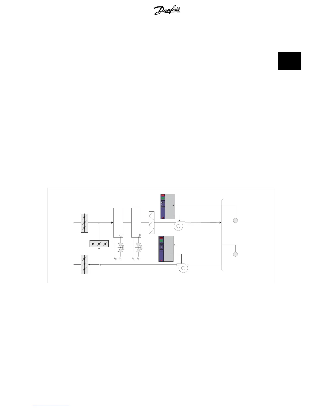
2.7.16 The VLT Solution
With a frequency converter, significant energy savings can be obtained while maintaining decent control of the building. Temperature sensors or CO
2
sensors can be used as feedback signals to frequency converters. Whether controlling temperature, air quality, or both, a CAV system can be controlled
to operate based on actual building conditions. As the number of people in the controlled area decreases, the need for fresh air decreases. The CO
2
sensor detects lower levels and decreases the supply fans speed. The return fan modulates to maintain a static pressure setpoint or fixed difference
between the supply and return air flows.
With temperature control, especially used in air conditioning systems, as the outside temperature varies as well as the number of people in the controlled
zone changes, different cooling requirements exist. As the temperature decreases below the set-point, the supply fan can decrease its speed. The return
fan modulates to maintain a static pressure set-point. By decreasing the air flow, energy used to heat or cool the fresh air is also reduced, adding further
savings.
Several features of the Danfoss HVAC dedicated frequency converter can be utilized to improve the performance of your CAV system. One concern of
controlling a ventilation system is poor air quality. The programmable minimum frequency can be set to maintain a minimum amount of supply air
regardless of the feedback or reference signal. The frequency converter also includes a 3-zone, 3 setpoint PID controller which allows monitoring both
temperature and air quality. Even if the temperature requirement is satisfied, the frequency converter will maintain enough supply air to satisfy the air
quality sensor. The controller is capable of monitoring and comparing two feedback signals to control the return fan by maintaining a fixed differential
air flow between the supply and return ducts as well.
Pressure
signal
Cooling coil
Heating coil
D1
D2
D3
Filter
Pressure
transmitter
Supply fan
Return fan
Temperature
signal
Temperature
transmitter
VLT
®
HVAC Drive Design Guide 2 Introduction to VLT HVAC Drive
MG.11.B9.02 - VLT
®
is a registered Danfoss trademark
27
2

 Loading...


