2.7.21 Primary Pumps
Primary pumps in a primary/secondary pumping system can be used to maintain a constant flow through devices that encounter operation or control
difficulties when exposed to variable flow. The primary/ secondary pumping technique decouples the “primary” production loop from the “secondary”
distribution loop. This allows devices such as chillers to obtain constant design flow and operate properly while allowing the rest of the system to vary in
flow.
As the evaporator flow rate decreases in a chiller, the chilled water begins to become over-chilled. As this happens, the chiller attempts to decrease its
cooling capacity. If the flow rate drops far enough, or too quickly, the chiller cannot shed its load sufficiently and the chiller’s low evaporator tempera-
ture safety trips the chiller requiring a manual reset. This situation is common in large installations especially when two or more chillers in parallel are
installed if primary/ secondary pumping is not utilized.
2.7.22 The VLT Solution
Depending on the size of the system and the size of the primary loop, the energy consumption of the primary loop can become substantial.
A frequency converter can be added to the primary system, to replace the throttling valve and/or trimming of the impellers, leading to reduced operating
expenses. Two control methods are common:
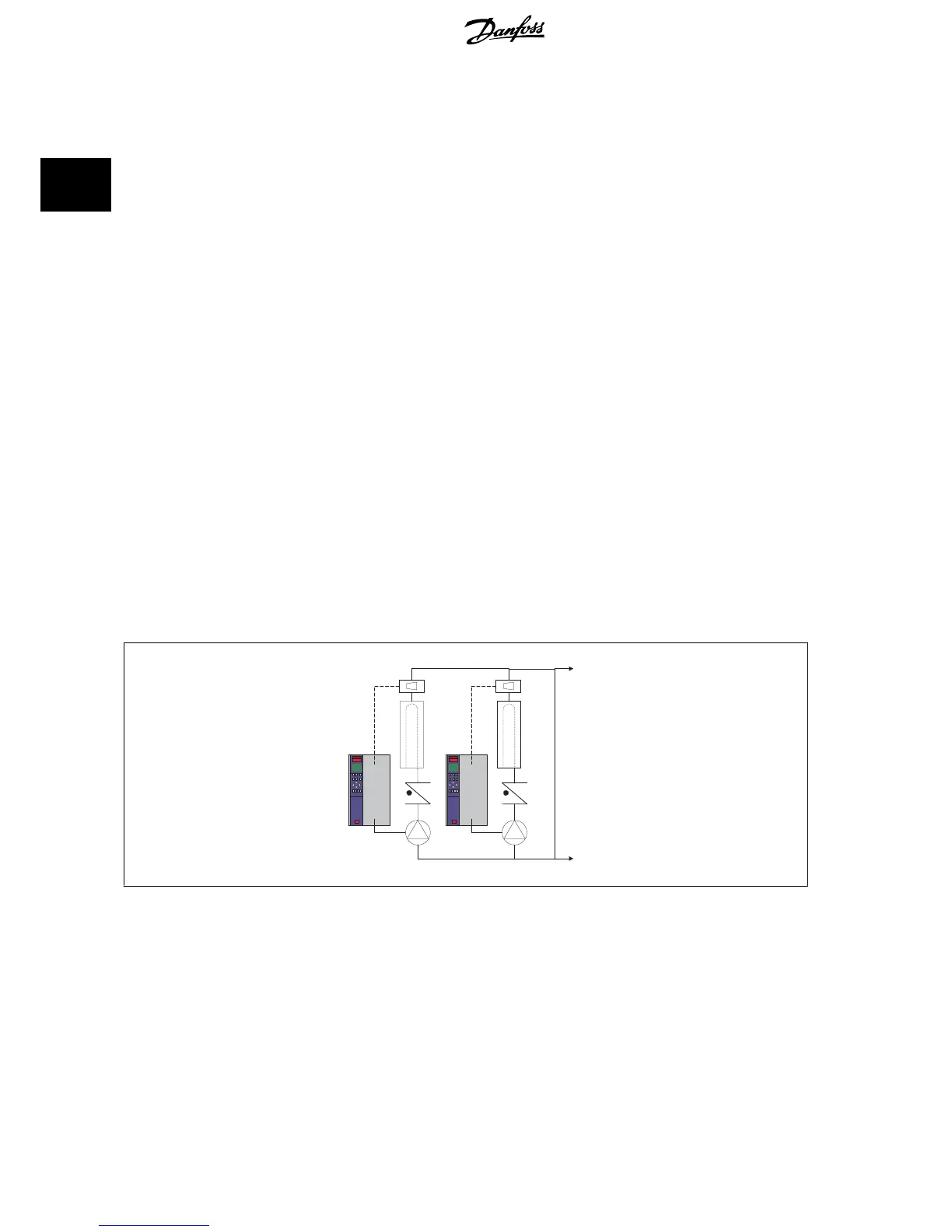
The first method uses a flow meter. Because the desired flow rate is known and is constant, a flow meter installed at the discharge of each chiller, can
be used to control the pump directly. Using the built-in PID controller, the frequency converter will always maintain the appropriate flow rate, even
compensating for the changing resistance in the primary piping loop as chillers and their pumps are staged on and off.
The other method is local speed determination. The operator simply decreases the output frequency until the design flow rate is achieved.
Using a frequency converter to decrease the pump speed is very similar to trimming the pump impeller, except it doesn’t require any labor and the pump
efficiency remains higher. The balancing contractor simply decreases the speed of the pump until the proper flow rate is achieved and leaves the speed
fixed. The pump will operate at this speed any time the chiller is staged on. Because the primary loop doesn’t have control valves or other devices that
can cause the system curve to change and the variance due to staging pumps and chillers on and off is usually small, this fixed speed will remain
appropriate. In the event the flow rate needs to be increased later in the systems life, the frequency converter can simply increase the pump speed
instead of requiring a new pump impeller.
CHILLER
F
CHILLER
F
Flowmeter
Flowmeter
2 Introduction to VLT HVAC Drive VLT
®
HVAC Drive Design Guide
30
MG.11.B9.02 - VLT
®
is a registered Danfoss trademark
2

 Loading...


