3.1.2 General Purpose Input Output Module MCB 101
MCB 101 is used for extension of the number of digital and analog inputs
and outputs of the frequency converter.
Contents: MCB 101 must be fitted into slot B in the frequency converter.
• MCB 101 option module
•Extended LCP frame
• Terminal cover
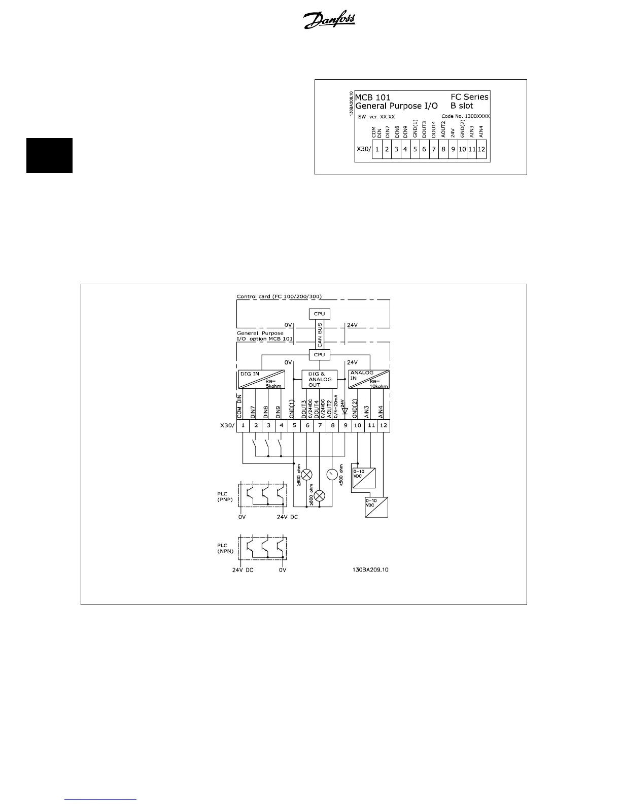
Galvanic Isolation in the MCB 101
Digital/analog inputs are galvanically isolated from other inputs/outputs on the MCB 101 and in the control card of the frequency converter. Digital/analog
outputs in the MCB 101 are galvanically isolated from other inputs/outputs on the MCB 101, but not from these on the control card of the frequency
converter.
If the digital inputs 7, 8 or 9 are to be switched by use of the internal 24 V power supply (terminal 9) the connection between terminal 1 and 5 which is
illustrated in the drawing has to be established.
Illustration 3.1: Principle Diagram
3 VLT HVAC Drive Selection VLT
®
HVAC Drive Design Guide
52
MG.11.B9.02 - VLT
®
is a registered Danfoss trademark
3

 Loading...


