3.1.7 Relay Option MCB 105
The MCB 105 option includes 3 pieces of SPDT contacts and must be fitted into option slot B.
Electrical Data:
Max terminal load (AC-1)
1)
(Resistive load) 240 V AC 2A
Max terminal load (AC-15 )
1)
(Inductive load @ cosφ 0.4) 240 V AC 0.2 A
Max terminal load (DC-1)
1)
(Resistive load) 24 V DC 1 A
Max terminal load (DC-13)
1)
(Inductive load) 24 V DC 0.1 A
Min terminal load (DC) 5 V 10 mA
Max switching rate at rated load/min load 6 min
-1
/20 sec
-1
1) IEC 947 part 4 and 5
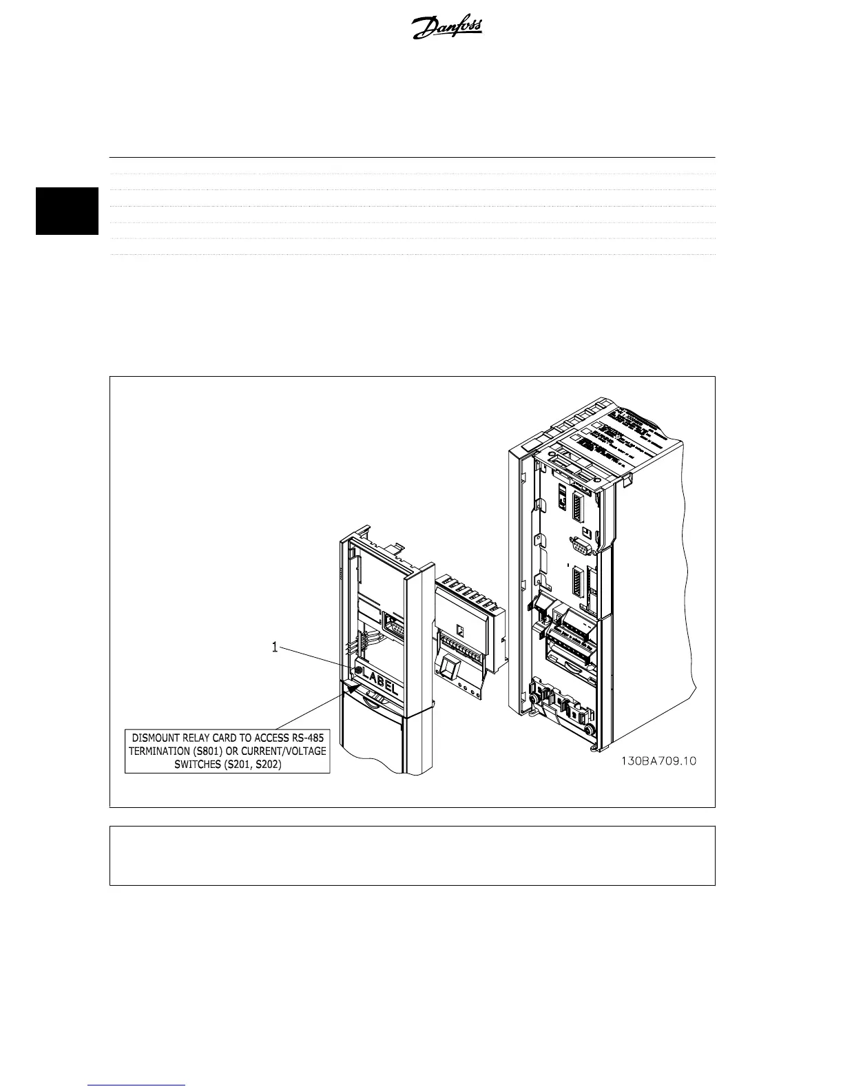
When the relay option kit is ordered separately the kit includes:
• Relay Module MCB 105
• Extended LCP frame and enlarged terminal cover
• Label for covering access to switches S201, S202 and S801
• Cable strips for fastening cables to relay module
A2-A3-B3 A5-B1-B2-B4-C1-C2-C3-C4
1)
IMPORTANT! The label MUST be placed on the LCP frame as shown (UL approved).
3 VLT HVAC Drive Selection VLT
®
HVAC Drive Design Guide
54
MG.11.B9.02 - VLT
®
is a registered Danfoss trademark
3

 Loading...


