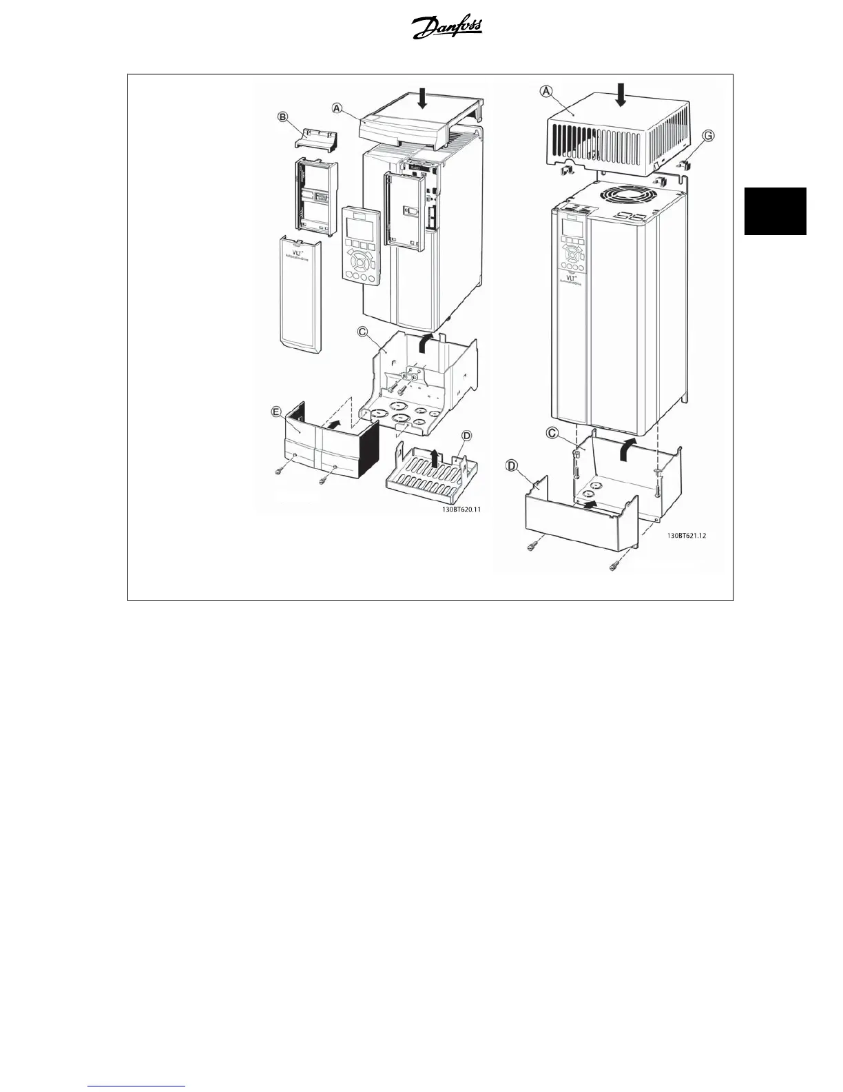
EasyManuals Logo

Danfoss VLT HVAC Design Guide

Danfoss VLT HVAC
200 pages
To Next Page IconTo Next Page
To Previous Page IconTo Previous Page
Page #63 background imageLoading...
Page #63 background image
A – Top cover
B – Brim
C – Base part
D – Base cover
E – Screw(s)
F - Fan cover
G - Top clip
When option module A and/
or option module B is/are
used, the brim (B) must be
fitted to the top cover (A).
B3 Enclosure B4 - C3 - C4 Enclosure
Side-by-side installation is not possible when using the
IP 21/ IP 4X/ TYPE 1 Enclosure Kit
VLT
®
HVAC Drive Design Guide 3 VLT HVAC Drive Selection
MG.11.B9.02 - VLT
®
is a registered Danfoss trademark
63
3

Table of Contents

Other manuals for Danfoss VLT HVAC

Questions and Answers:

Question and Answer IconNeed help?

Do you have a question about the Danfoss VLT HVAC and is the answer not in the manual?

Danfoss VLT HVAC Specifications

General IconGeneral
Enclosure RatingIP20, IP21, IP54, IP55, IP66
Storage Temperature Range-25°C to +70°C
Output Voltage Range0-100% of supply voltage
Communication ProtocolsModbus RTU, BACnet, Ethernet/IP, Profibus DP
Ambient Temperature Range-10°C to +50°C (without derating)
Relative Humidity5% to 95% non-condensing
AltitudeUp to 1000 m without derating
Cooling MethodAir cooled
ApplicationHVAC systems, Pumps, Fans, Compressors
Voltage Range200-240 V, 380-500 V, 525-600 V
Frequency Range0 Hz to 590 Hz

Related product manuals