EasyManuals Logo

Danfoss VLT HVAC Design Guide

Danfoss VLT HVAC
200 pages
To Next Page IconTo Next Page
To Previous Page IconTo Previous Page
Page #80 background imageLoading...
Page #80 background image
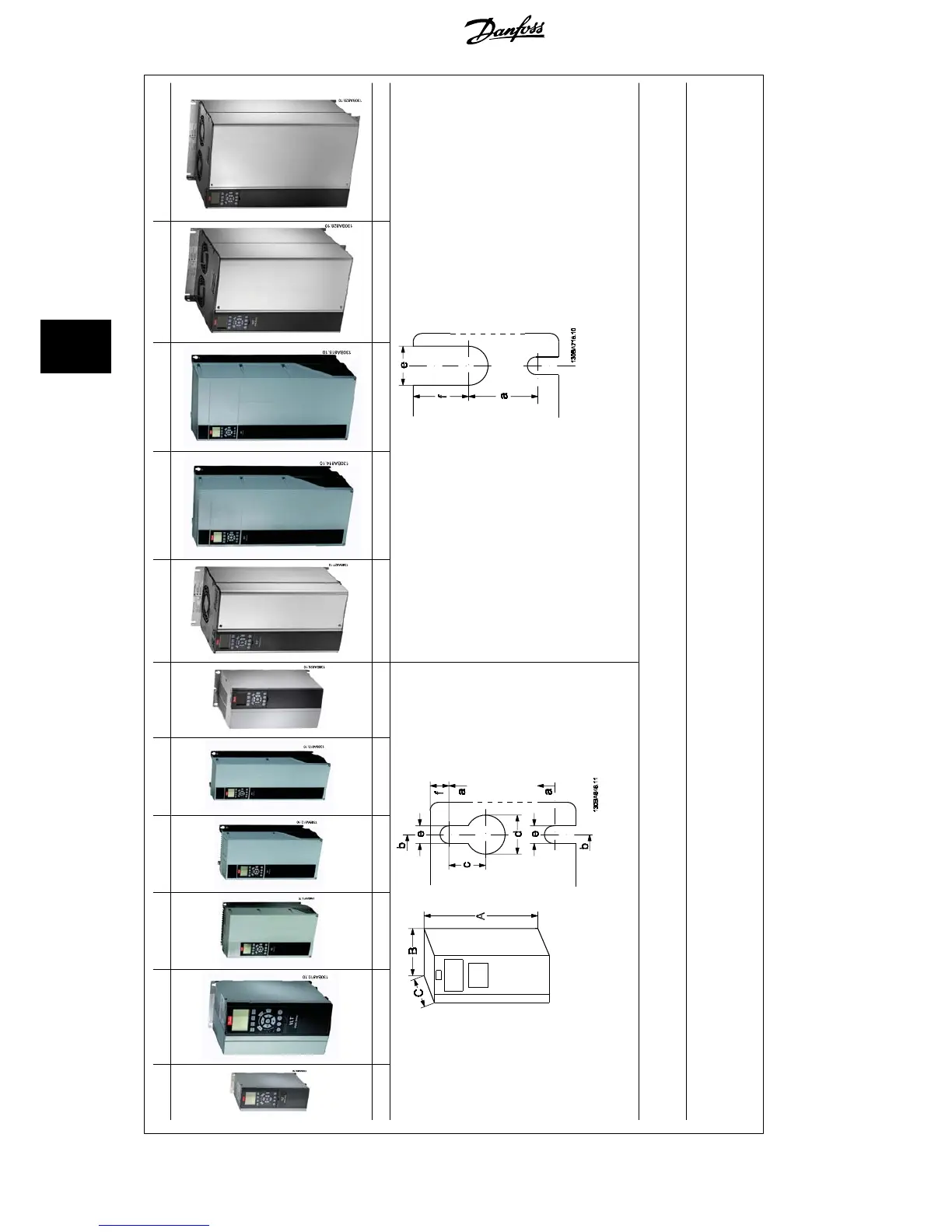
A2 A3 A5 B1 B2 B3 B4 C1 C2 C3 C4
IP20/21* IP20/21* IP55/66 IP21/55/66 IP21/55/66 IP20/21* IP20/21* IP21/55/66 IP21/55/66 IP20/21* IP20/21*
Illustration 5.1: Top and bottom mounting holes.
Illustration 5.2: Top and bottom mounting holes. (B4+C3+C4 only)
Accessory bags containing necessary brackets, screws and connectors are included with the drives upon delivery.
All measurements in mm.
* IP21 can be established with a kit as described in the section: IP 21/ IP 4X/ TYPE 1 Enclosure Kit in the Design Guide.
5.1.1 Mechanical front views
5 How to Install VLT
®
HVAC Drive Design Guide
80
MG.11.B9.02 - VLT
®
is a registered Danfoss trademark
5

Table of Contents

Other manuals for Danfoss VLT HVAC

Questions and Answers:

Question and Answer IconNeed help?

Do you have a question about the Danfoss VLT HVAC and is the answer not in the manual?

Danfoss VLT HVAC Specifications

General IconGeneral
Enclosure RatingIP20, IP21, IP54, IP55, IP66
Storage Temperature Range-25°C to +70°C
Output Voltage Range0-100% of supply voltage
Communication ProtocolsModbus RTU, BACnet, Ethernet/IP, Profibus DP
Ambient Temperature Range-10°C to +50°C (without derating)
Relative Humidity5% to 95% non-condensing
AltitudeUp to 1000 m without derating
Cooling MethodAir cooled
ApplicationHVAC systems, Pumps, Fans, Compressors
Voltage Range200-240 V, 380-500 V, 525-600 V
Frequency Range0 Hz to 590 Hz

Related product manuals