CR500 Instant Issuance System Installation and Administrator’s Guide 17
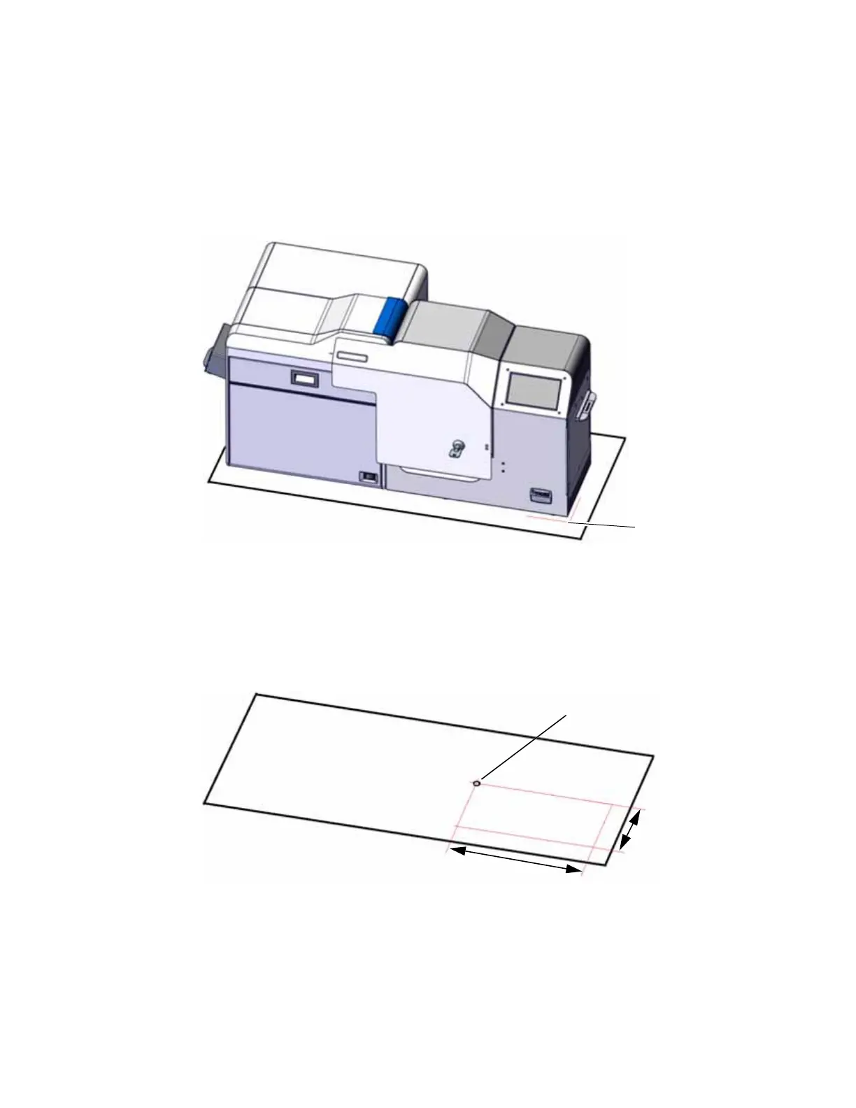
1. Place the printer in the desired location on the work surface. Refer to “Ventilation Clearance”
on page 11 for clearance requirements.
2. Mark the bolt-down hole location and drill the hole:
a. Mark the front-right corner of the printer on the work surface.
b. Measure and mark the following points on the work surface:
Along the front of the printer, 9-7/16 inch (240 mm) from the front-right corner.
Along the right side of the printer, 3-5/16 inch (83 mm) from the front-right corner.
c. Move the printer and use the marked points to locate the bolt hole position.
d. Drill the bolt hole.
3. Place the printer over the drilled hole, aligning the front-right corner with the marked
location from step 2a.
Mark this corner on
the work surface.
Mark and drill the bolt-
down hole here.
9
-
7
/1
6
i
n
.
(
2
4
0
m
m
)
3-5/16 in. (83 mm)
 Loading...