Introduction
2
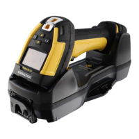
BC9180™ Base Station/Charger
The BC9180™ Base Station/Charger
The BC9180™ base station, when paired with one or more PowerScan™
9500 readers, builds a Cordless Reading System for the collection,
decoding and transmission of bar code data. It can be connected to a
Host PC via Ethernet Host Interface. The BC91x0 models also provide a
spare battery charger slot.
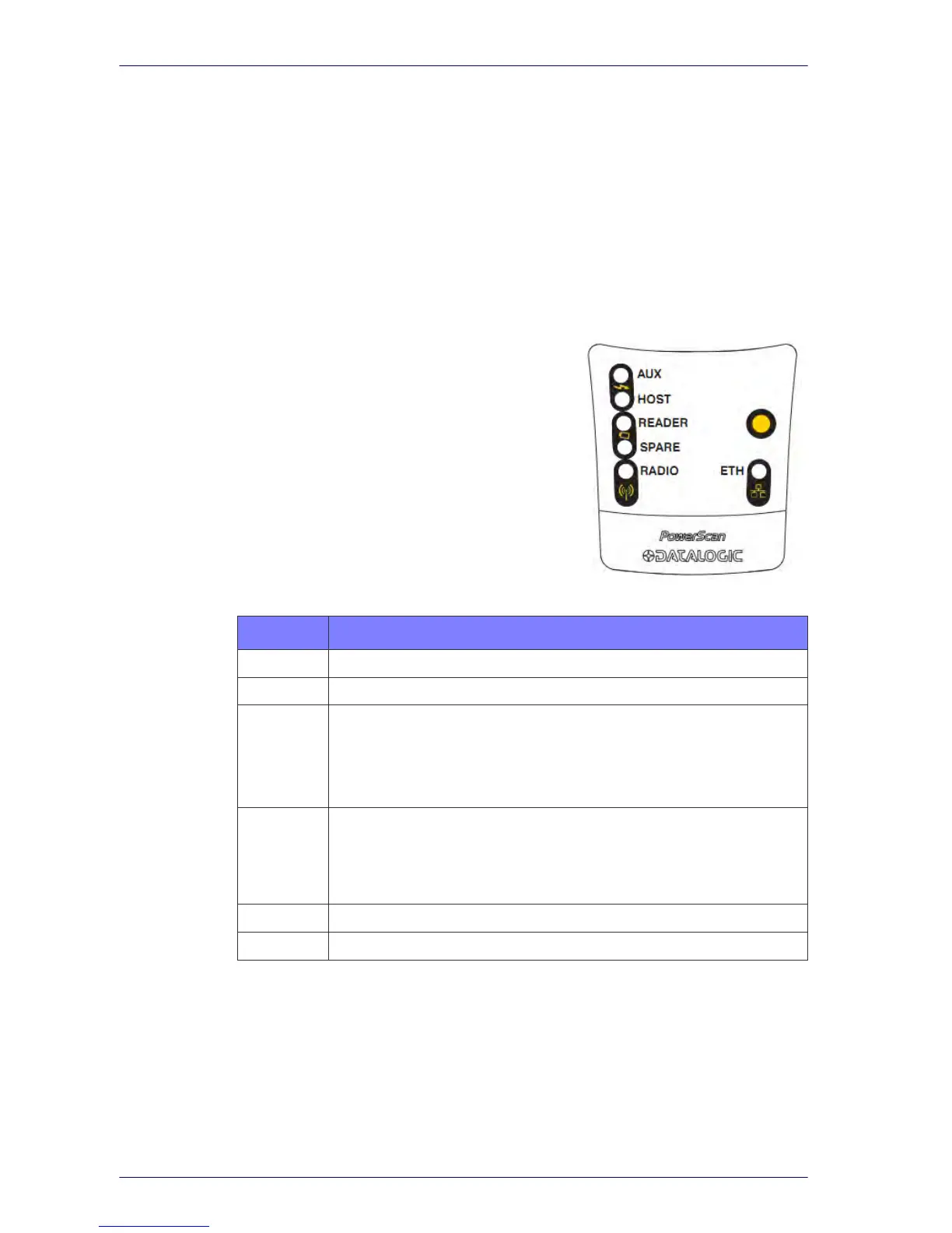
The label on the cradle contains LED in
dicators and a multi-function but-
ton. When the button is pressed for less than 5 seconds, the cradle will
transmit a "broadcast" message." When the broadcast is sent, all properly
configured scanners that are linked to that base and within radio range
coverage will emit a beep and blink within 5 seconds. This functionality is
useful for:
• Verifying which scanners are linked to
a
certain base station
• Paging (detect the position of linked
scanners)
The LEDs signal the BC9180 status, as
sho
w
n in
Table 1.
Table 1. LED Status
LED STATUS
Aux Yellow On = BC9180 is powered through an external power supply.
Host Yellow On = BC9180 is powered by the Host.
Reader
Green On = the reader battery is completely charged.
Red On = the reader battery is charging.
Red / Green Alternatively Blinking = charging error.
Off = reader not in the cradle or not properly inserted.
Spare
Green On = the spare battery is completely charged.
Red/Green Alternatively Blinking = charging error - see "
Error Codes" on
page 320
.
Off = no spare battery in the housing or battery not fully inserted.
Radio Yellow Blinking = radio activity.
Ethernet Green Blinking = Ethernet activity.
 Loading...