Appendix J – General Purpose Input Output Port Applications
258 Class Series 2 Programmer’s Manual
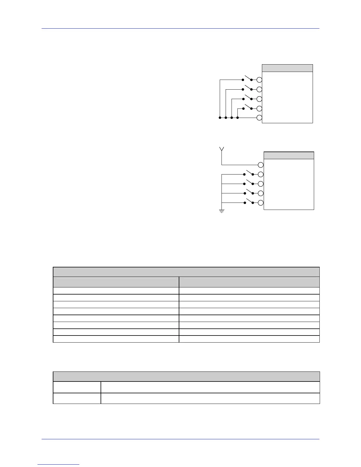
The Start of Print Circuit depends upon the applicator system’s requirements:
• For direct inputs –
Use the printer’s +5VDC and Ground to supply
the devices interfacing to the GPIO inputs (as
shown, right).
J2 - GPIO PORT
3
4
5
6
1
Start of Print
Slew Label
Pause Toggle
Reprint
Ground
• For isolated inputs –
Supply an external +5 VDC and ground,
remove JMP 7 and JMP 8 from the Applicator
Interface Card and follow the schematic shown
right.
3
4
5
6
2
Start of Print
Slew Label
Pause Toggle
Reprint
Vcc
Vcc = 5 VDC External Power Source
Ground
J2 -GPIO PORT
The Auxiliary Port (J1) is an RS-232 interface. Serial data transfer settings (such as baud
rate, word length, and parity) can be made using <STX>KcSP commands. These settings
must match the device that you are connecting. Jumpers JMP 1 – JMP 4 should be in
installed.
Applicator Interface Card (Type 1) Auxiliary Data Port
Pin Number(s) Signal
1 +5 VDC (0.5 Amp )
2 RX
3 TX
4 DTR
5 Ground
6 & 9 N/C
7 RTS
8 CTS
Indicators: The LEDs provide a visual indication of printer/applicator signal activity:
Applicator Interface Card (Type 1) Indicators
• Yellow LED
Flash at power-up and when the outputs change state.
• Green LED
Flash at power-up and when the inputs change state.
 Loading...