Appendix J – General Purpose Input Output Port Applications
260 Class Series 2 Programmer’s Manual
GPI/O A (J1)
Four dedicated inputs are available for control of printer functions. These inputs require
no external pull-ups, are designed to interface to open-collector outputs and accept totem
pole outputs from +4.5 to + 26 VDC. Optical isolators are available to provide isolation. Two
print control circuit examples are given below.
•
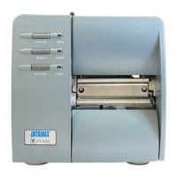
For direct inputs –
Use the printer’s +5VDC and Ground to supply
the devices interfacing to the GPI/O A inputs
(as shown, right).
GPI/O A - J1
3
4
5
6
1
Start of Print
Slew Label
Toggle/Pause
Reprint
Ground
•
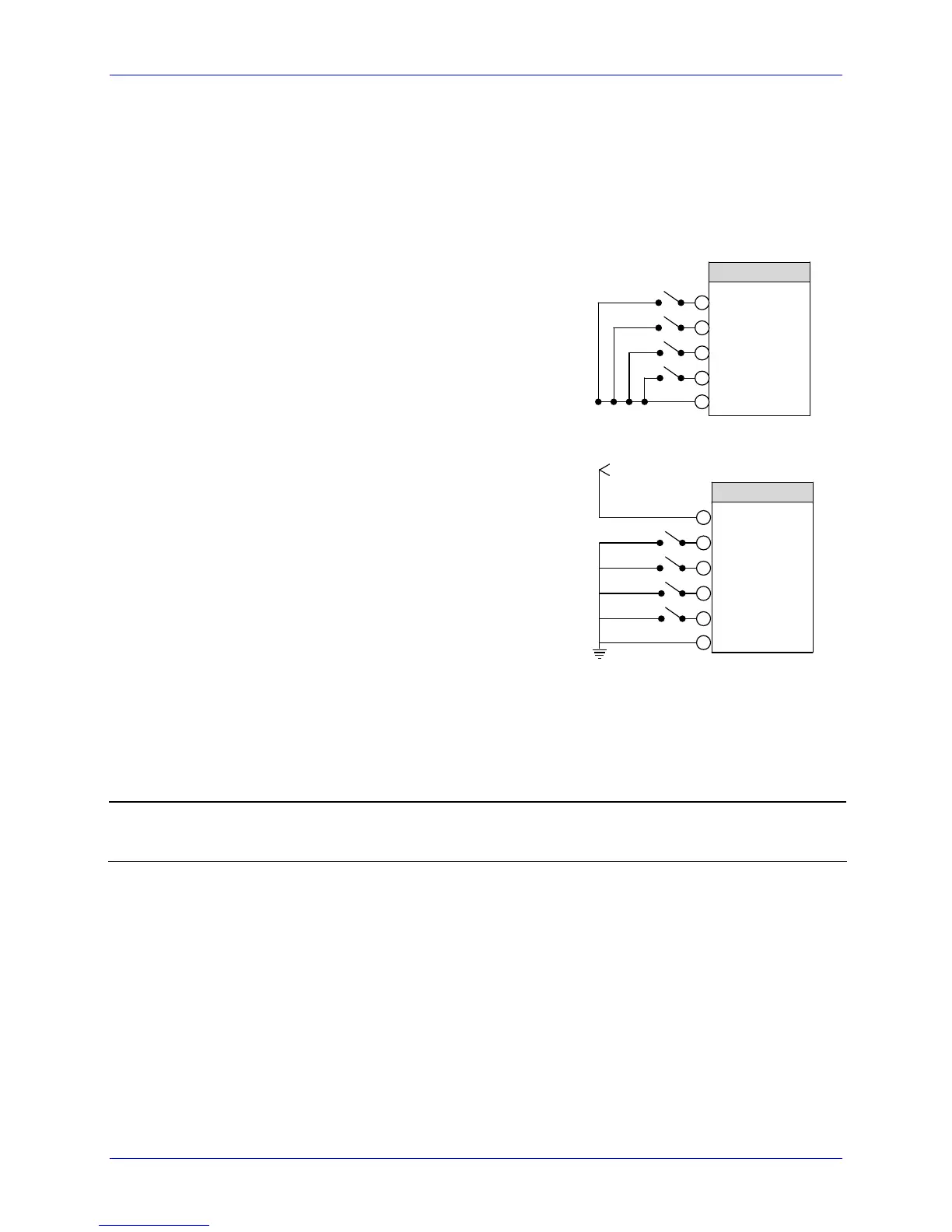
For isolated inputs –
To provide galvanic isolation for the GPI/O A
inputs, remove jumper JMP 9 then supply an
external +5VDC source voltage to Pin 2, and
remove jumper JMP 8 then supply an external
Ground to Pin 1 (as shown, right).
3
4
5
6
2
Start of Print
Slew Label
Toggle/Pause
Reprint
Vcc
+5 VDC External Source
GPI/O A - J1
1
Ground
Seven dedicated outputs are available for control, warning, and error functions. These
open-collector outputs are slew-limited. Optional 10K ohm pull-up resistors, tied to a
common point for use at either +5 or +24 VDC, are available via jumper JMP 1.
To avoid damage if external pull-up resistors are used (that is, without jumper JMP1
installed), ensure that the external voltage does not exceed +30VDC.
The table below details the GPI/O A pin assignments, settings and functions:
 Loading...