AP20 Installation and Operating Guide Version 1.25
Appendix A. Connector Pin-outs A-1 Document #: 9301H39200 Ver. 1.25
Appendix A. Connector Pin-outs
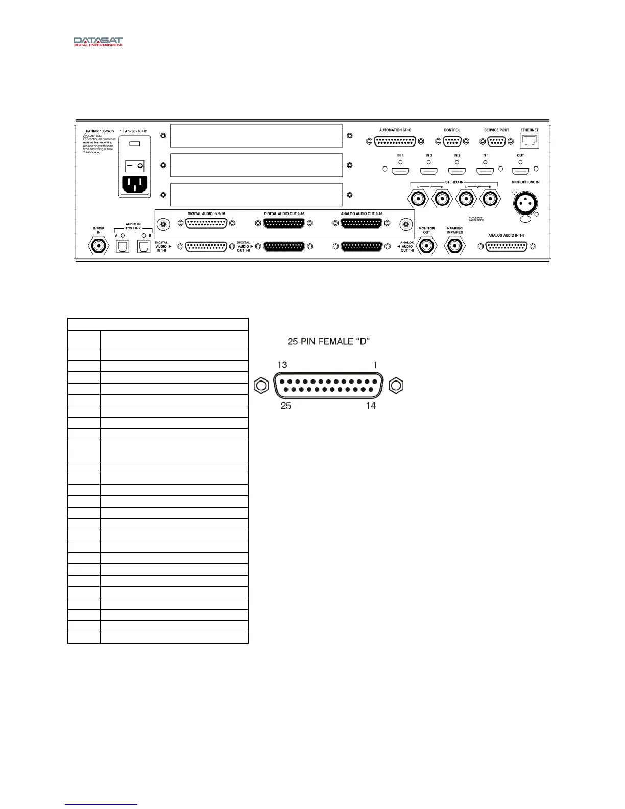
This appendix lists the pin-out of all of the connectors on the back panel of the AP20 Audio Processor.
Figure 1. AP20 Rear Panel
AUTOMATION GPIO – DB25F
Pin Description
1 GPIO 1 (Format 0)
2 GPIO 2 (Format 1)
3 GPIO 3 (Format 2)
4 GPIO 4 (Format 3)
5 GPIO 5 (Format 4)
6 GPIO 6 (Format 5)
7 GPIO 7 (Format 6)
8 GPIO 8 (Format 7)
9 GPIO 17 (Format Remote Fader
Enable)
10 GPIO 18 (Format MUTE Enable)
11 N/C
12 AP20 GND
13 AP20 Ext. 5 volts (140mA. max)
14 GPIO 9 (Format ID 0)
15 GPIO 10 (Format ID 1)
16 GPIO 11 (Format ID 2)
17 GPIO 12 (Format ID 3)
18 GPIO 13 (Format ID 4)
19 GPIO 14 (Format ID 5)
20 GPIO 15 (Format ID 6)
21 GPIO 16 (Format ID 7)
22 GPO 19 (Remote Fader Talley)
23 GPO 20 (MUTE Talley)
24 N/C
25 PROJECTOR C/O (1 / 2)
N/C = No connection