AP20 Installation and Operating Guide Page 90
AP20 Installation & Operating Guide Document # 9301H39200 Ver. 1.25
4. Set High pass filter. Options are Off, 6, 12, 18, and 24 dB/octave and from 20Hz to 20kHz.
High pass filters can be used even if crossover is not selected.
5. Set Output Channel Trim. The Output channel trim may be set from 0dB to -10dB in
0.5dB increments. The output trim may be used to balance the levels of crossover
channels.
Note: The output channels are assigned one of the following letter IDs (Crossover ID): W, L,
M, H, and 0-9. This is used for reference for the output channel and has no functional purpose
at this time.
4.3.8.4.4. Example Crossover Setup
When setting
up the AP20 crossovers, you will need to identify the speaker model used and
obtain its technical specifications. Speaker technical specifications can usually be found on the
manufacturer’s web site.
In this example, we are setting up the AP20 Left channel, input 1, for 3-way crossover using
the model JBL 2632-T speaker. There are three main steps to this process, as shown below. The
specification sheet for the JBL 2632-T lists its frequency range as 30Hz to 20kHz and crossover
frequencies as 350Hz and 1.2kHz.
Low Frequency
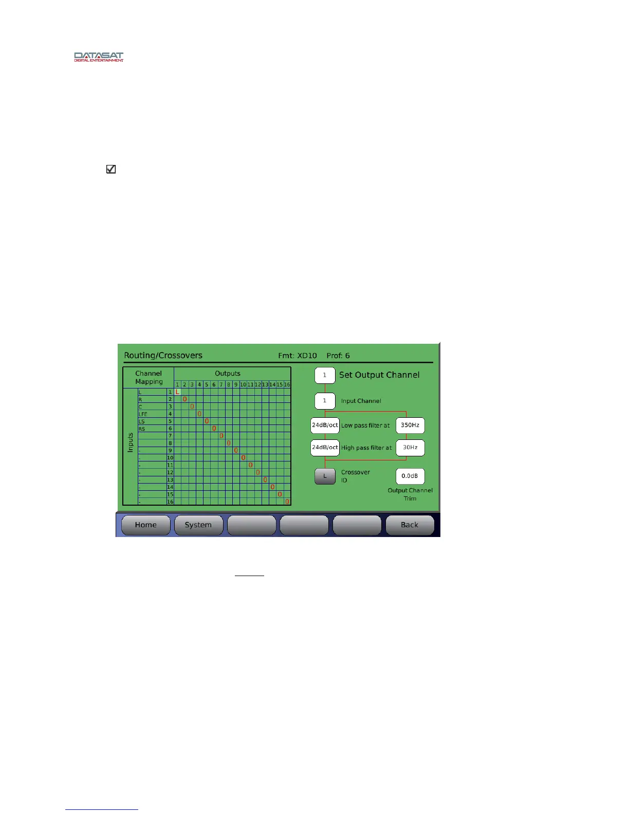
Figure 68. Example – Low Frequency Crossover Setup
As shown in Figure 68, set output channel 1 for the low frequency driver. To make changes
select a box by touching it and use the fader to change it’s value.
The low pass filter should be set to the upper crossover point of the low frequency driver which
in this case (for JBL 2632-T) is 350Hz.
If the manufacturer indicates a particular slope then use it. In this case, JBL didn’t list a slope so
we chose 24dB/octave.
Depending on the speaker, you may choose to add a high pass filter to block low frequencies. In
this case, we chose to put a high pass filter to 30Hz, to block frequencies below the lower
capabilities of this driver although this is not deemed necessary by the manufacturer.
Set the crossover ID for easy identification. Here we set the crossover ID for channel 1 output L
which identifies it as the low frequency output for channel one (1). This is only a label for easy
identification and does not affect the crossover itself.