AP20 Installation and Operating Guide Page 92
AP20 Installation & Operating Guide Document # 9301H39200 Ver. 1.25
Set the slope to 24dB/octave.
Set the Crossover ID to H to identify it as the high frequency output for channel three (3). Note:
We also set the low pass filter to 1.2kHz, the upper range of the speaker, for added protection
although it was not specified as necessary by the manufacturer.
The main fader level adjust will change the level on the input channel, in this example = left
channel. When adjusting the fader, all output channels assigned to an input channel will
change by the same amount.
The output channel trim can be used to lower an individual output channel.
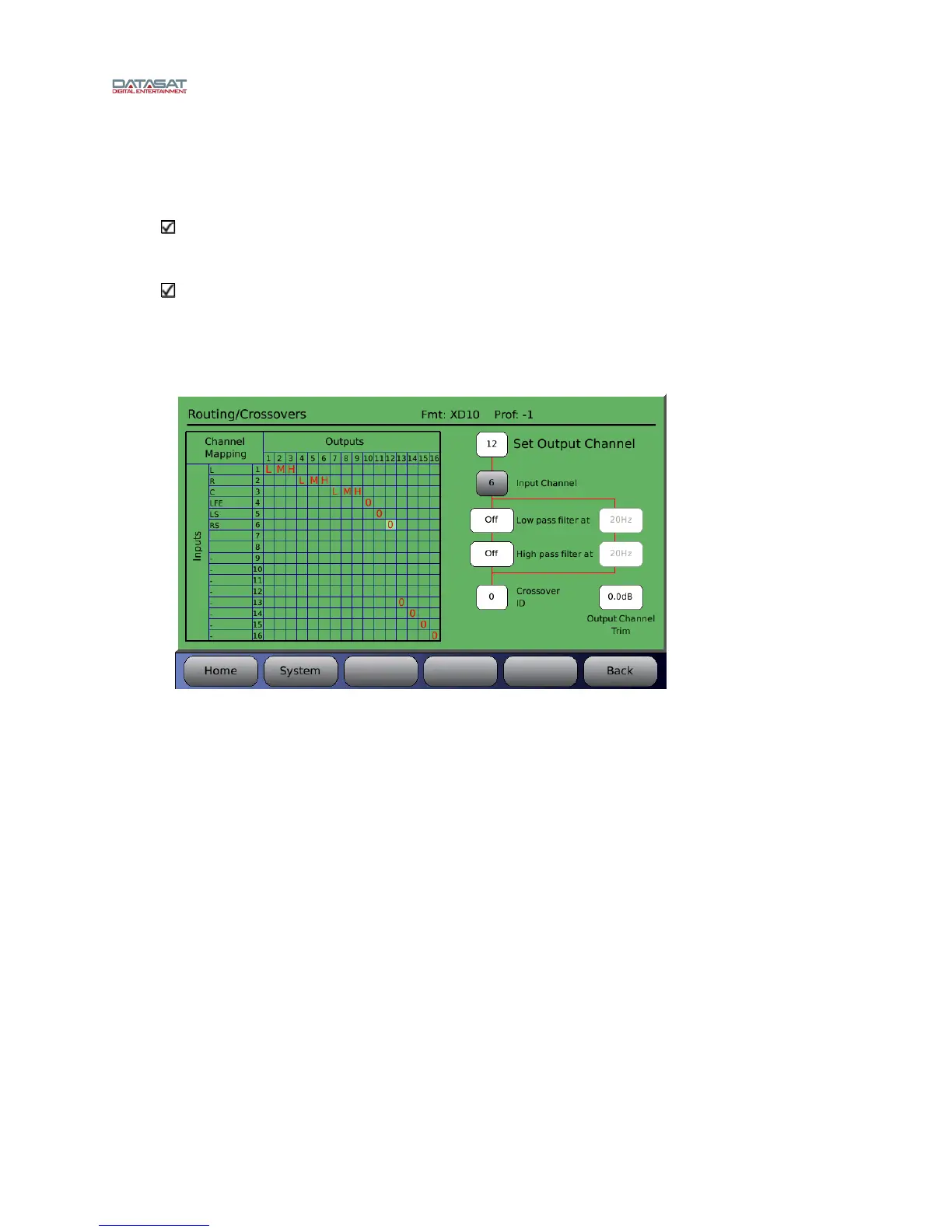
Figure 71 below shows a typical example of a completed routing/crossover setup in which the
screen chann
els (left, right, center) have been tri-amped. The LFE, LS and RS channels have
been routed to output channels 10, 11, and 12 (no low or high pass filters have been applied to
these channels).
Figure 71. Example – Crossover Setup