Service Diagnostics Calibration
5 - 8 0070-10-0691 Accutorr Plus Service Manual
5.5.4 LED Test (2a, 2b)
This test allows the LED function to be verified by driving all seven LEDs with numbers
from 0 to 9, in sequential order. For this test, all annunciator LEDs turn on for 1 second.
5.5.5 Communication Test (3a, 3b)
This test checks the integrity of the external communication systems. Test 3a checks the
external RS232 interface and requires that the transmit and receive pins be connected
together. Test 3b checks the Download port and requires that the tip (transmit) and ring
(receive) pins be connected together. The CRC table is transmitted and received. If the
CRC data received matches the CRC table transmitted, the test passes; otherwise a failure
is reported.
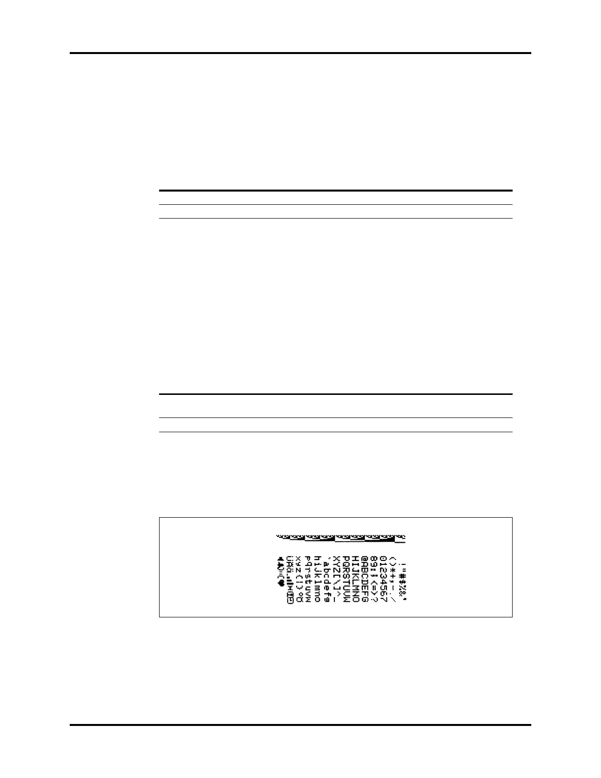
5.5.6 Recorder Test (4)
1. Select Room Number 4 and press the NIBP START key to activate the test. This test
prints out a pattern on the recorder if a recorder module is attached. A strip similar to
Figure 5-3 will be printed.
FIGURE 5-3
Table 5-3
TEST DESCRIPTION TEST ROOM NUMBER
SUB TEST PATIENT
BED LETTER
7 Segment LED Test 2 a
Annunciator LED Test 2 b
Table 5-4
TEST DESCRIPTION
SHORT
CONNECTOR PINS
TEST ROOM
NUMBER
SUB TEST
PATIENT BED
LETTER
RS232 Port Test Transmit (2) and
Receive (3)
3a
Download Port Test Tip and Ring 3 b