Do you have a question about the Datex-Ohmeda 7900 and is the answer not in the manual?
Covers manual's scope, disclaimer, technical competence, and special notices.
Defines manual terms and lists common symbols used throughout the document.
Details manual contents and ventilator configuration, including software versions.
Outlines general service procedures, tests, and calibration methods for the ventilator.
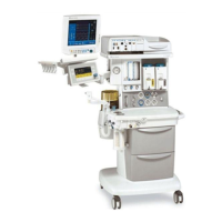
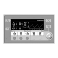
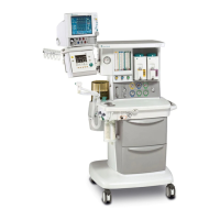
Describes the overall function and interface of the 7900 ventilator system.
Details supply gas, valves, regulators, and manifolds within the pneumatic system.
Lists electrical modules and provides the electronic block diagram of the system.
Details the power supply, step-down regulator, and battery operation.
Explains CPU, memory, I/O, and system clock functionalities.
Describes watchdog timers and error handling mechanisms for system reliability.
Details ADC, DAC, and related components for data processing.
Covers flow valve control, GIV drive, display interface, and alarms.
Explains SIB role in flow, pressure, and O2 measurements.
Emphasizes critical post-service checks for patient safety and system integrity.
Outlines procedures for testing the ventilator, anesthesia system, and accessories.
Introduces tests and prerequisites for performing diagnostic tests on the ventilator.
Instructions on entering and navigating the service mode menu for diagnostics and calibration.
Details specific tests for CPU, RAM, ROM, panel switches, ports, and valves.
Describes tools like A/D display, I/O signals, error log, and error codes for troubleshooting.
Step-by-step guides for O2 sensor, flow sensors, pressure, flow valve, and bleed resistor calibration.
Covers user-configurable settings like altitude and drive gas, and exiting service mode.
Guide for diagnosing and resolving mechanical and electrical problems based on symptoms.
Guide for addressing issues based on system alarm messages and their probable causes.
Outlines yearly and two-year maintenance checks and component replacements.
Details maintenance for exhalation valve, supply gas inlet filter, and free breathing valve.
Essential notes, warnings, and tools required for performing repairs on the ventilator.
Instructions for removing the ventilator from integrated and non-integrated systems.
Guidance on setting up and using the service shelf for safe ventilator maintenance.
Covers top cover, circuit boards, power module, and transformer removal procedures.
Details removal and repair of pneumatic components like valves and regulators.
Steps for removing the Sensor Interface Board (SIB) and interface harnesses.
Procedures for testing the unit after repair and performing post-service checkout.
Lists common parts, special installation instructions, and available service kits.
Visual breakdown of key components like covers, panels, power modules, and pneumatic parts.
Lists different SIB harnesses and associated part numbers.
Overall block diagram showing system interconnections.
Detailed schematics for SIB interface cables and routing.
Detailed schematic diagrams for the microcontroller board.
Detailed schematic diagrams for the power supply board.
Lists various accessory and bellows mounting kits with part numbers.
Lists available O&M manuals in different languages and revisions.
| Type | Ventilator |
|---|---|
| Ventilation Modes | Volume Control, Pressure Control, SIMV |
| Oxygen Concentration | 21-100% |
| Respiratory Rate Range | 1-150 breaths/min |
| PEEP Range | 0-20 cmH2O |
| Power Supply | 100 to 240 VAC, 50/60 Hz |