6/ Repair Procedures
1503-0151-000 5/26/0 6-19
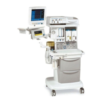
Removing the front panel
1. Disconnect the ribbon cable (J2) from the front panel.
2. Use the 2.5 mm hex wrench to remove the two chassis mounting screws.
Figure 6-14
Front panel removal
3. Lift the front panel up to clear mounting pins and remove it from the chassis.
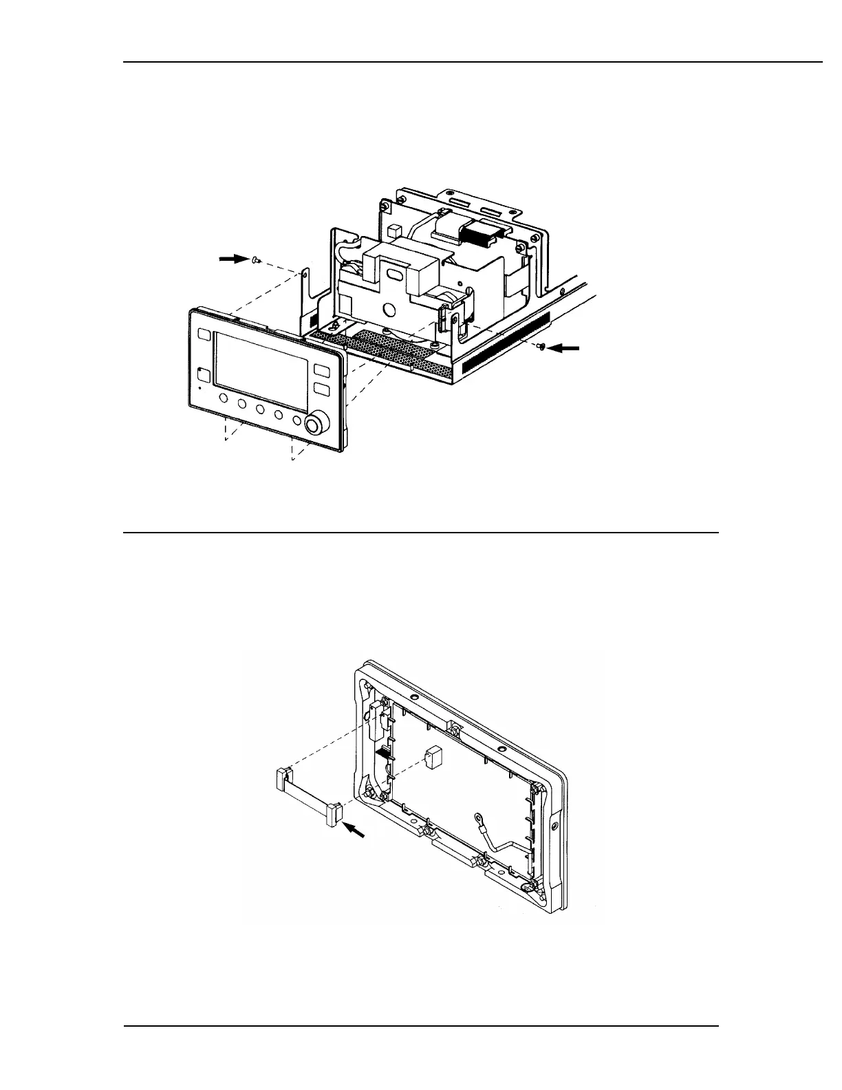
Replacing the display board
1. Disconnect the ground wire from the front panel board using the 7 mm nut
driver.
Figure 6-15
Disconnect cable.
2. Disconnect ribbon cable between display board and keyboard board.
Squeeze locking tabs to release connectors.
 Loading...