6/ Repair Procedures
1503-0151-000 5/26/0 6-39
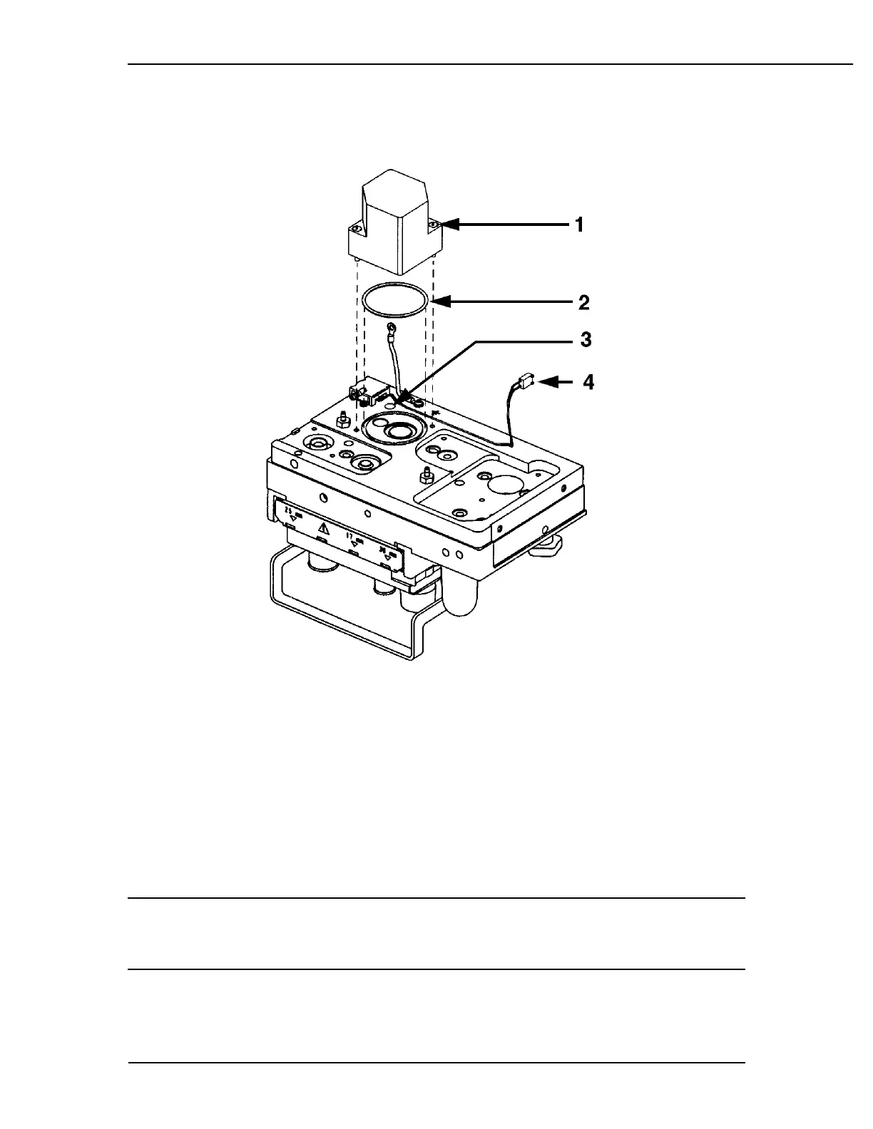
Removing the Drive gas check valve assembly
1. Captive mounting screws
2. O-ring
3. Alignment hole
4. Pressure switch harness
Figure 6-33
Drive gas check valve removal
CAUTION w The internal components of the Drive Gas Check Valve are precisely po-
sitioned. Do not attempt to remove or reposition the glass sleeve or pis-
ton assembly.
 Loading...