4. Hardware
4.1 Board slot positions
The unit housing is divided into board slot positions. This means that the unit consists of a number of printed
circuit boards (PCBs) mounted in numbered slots. The green terminal blocks are then mounted in the PCBs.
Some of these board slots are standard and some are intended for options. The board slot positions are ar-
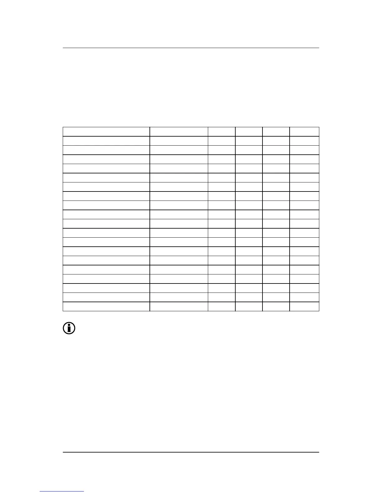
ranged as illustrated below.
Slot type Option Slot #1 Slot #3 Slot #5 Slot #7
Terminals 1-28 37-64 73-89 98-125
Power supply Standard X
AC measurements Standard X
Engine interface Standard X
Load sharing G3 X
Power management G4/G5/G8 X
Engine communication H7 X
I/O extension M12 X
Slot type Option Slot #2 Slot #4 Slot #6 Slot #8
Terminals 29-34 65-72 90-97 126-133
Analogue controller outputs E1/E2 X
Analogue transducer outputs F1 X
Combination outputs EF2/EF4/EF5/EF6 X
Serial communication H2/H3/H8.2 X
Engine communication H5/H6 X
I/O extension cards M13.2 X
I/O extension cards M13.6/M14.6/M15 X
I/O extension cards M13.8/M14.8/H8.8 X
Plant management G7 X
Only hardware options, which will affect the hardware of the unit, are represented in the table.
The software options will be seen through the PC utility software. The software options that are
not represented in the above table can be found in the data sheet.
AGC-3 installation instructions 4189340728
UK
Hardware
DEIF A/S Page 15 of 65