4.1.3 Input/output lists
In the I/O lists, the following terms will be used in connection with the relay outputs:
NO means Normally Open
NC means Normally Closed
NE means Normally Energised
ND means Normally Deenergised
Com. means common terminal
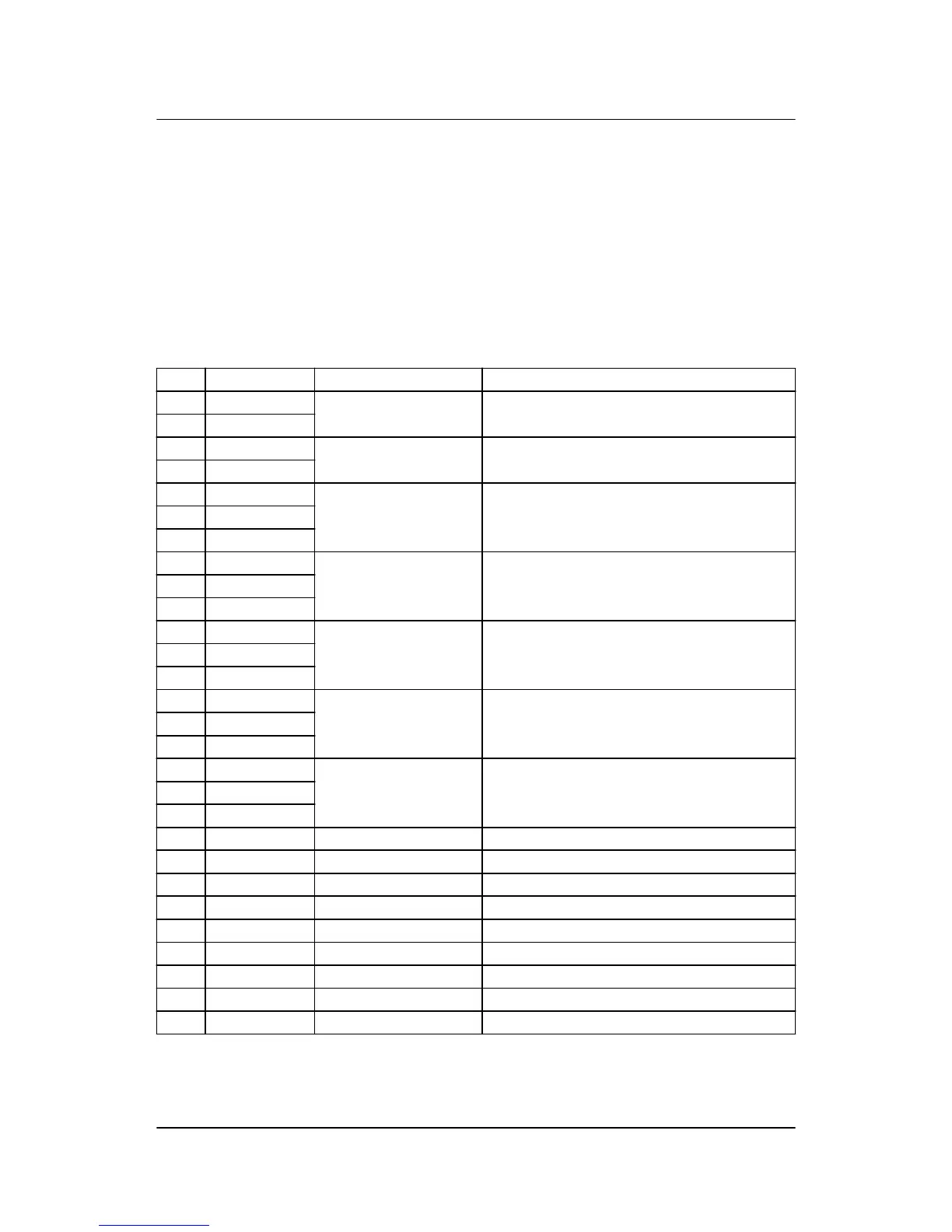
4.1.4 Slot #1, power supply PCB
Term. Function Technical data Description
1 +12/24 V DC 12/24 V DC
+/-30 %
Power supply
2 0 V DC
3 NO Status relay
24 V DC/1 A
Normally open relay, processor/power supply sta-
tus supervision
4 Com.
5 NO Relay 05
250 V AC/8 A
Central alarm HORN/configurable
6 Com.
7 NC
8 NO Relay 08
250 V AC/8 A
Open mains breaker/configurable
9 Com.
10 NC
11 NO Relay 11
250 V AC/8 A
Close mains breaker (synchronising)/configurable
12 Com.
13 NC
14 NO Relay
250 V AC/8 A
Open generator breaker
15 Com.
16 NC
17 NO Relay
250 V AC/8 A
Close generator breaker (synchronising)
18 Com.
19 NC
20 Open collector 1 Transistor output/Relay 20 Pulse output 1, kWh counter/configurable
21 Open collector 2 Transistor output/Relay 21 Pulse output 2, kvarh counter/configurable
22 Com. Common Common terminal for terminals 20 and 21
23 Digital input 23 Optocoupler Configurable
24 Digital input 24 Optocoupler Mains breaker open/configurable
25 Digital input 25 Optocoupler Mains breaker closed/configurable
26 Digital input 26 Optocoupler Generator breaker open
27 Digital input 27 Optocoupler Generator breaker closed
28 Com. Common Common for terminals 23 to 27
AGC-3 installation instructions 4189340728
UK
Hardware
DEIF A/S Page 23 of 65