4.1.1 Unit top side overview
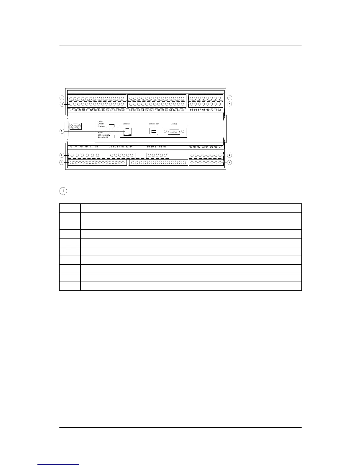
An overview of the terminals is presented below. The slot positions are as follows:
:
The numbers in the drawing above refer to the slot numbers indicated in the table below.
No. Slot
1 #1, terminal 1-28, power supply (standard)
2 #2, terminal 29-36, communication
3 #3, terminal 37-64, inputs/outputs/load sharing
4 #4, terminal 65-72, governor, AVR, inputs/outputs (standard)
5 #5, terminal 73-89, AC measuring (standard)
6 #6, terminal 90-97, inputs/outputs
7 #7, terminal 98-125, engine I/F (standard)
8 #8, terminal 126-133, engine communication, inputs/outputs
9 LED I/F
AGC-3 installation instructions 4189340728
UK
Hardware
DEIF A/S Page 16 of 65