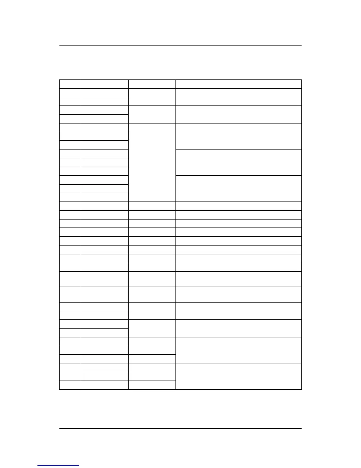
4.1.24 Slot #7, engine interface card (standard)
Term. Function Technical data Description
98 +12/24 V DC 12/24 V DC
+/-30 %
DC power supply
99 0 V DC
100 MPU input 0.5 to 70 V AC/
10 to 10,000 Hz
Magnetic pickup
101 MPU GND
102 A 0(4) to 20 mA
Digital
Pt100
Pt1000
RMI
0 to 40 V DC
Multi-input 1
103 B
104 C
105 A Multi-input 2
106 B
107 C
108 A Multi-input 3
109 B
110 C
111 Com. Common Common for terminals 112-117
112 Digital input 112 Optocoupler Configurable
113 Digital input 113 Optocoupler Configurable
114 Digital input 114 Optocoupler Configurable
115 Digital input 115 Optocoupler Configurable
116 Digital input 116 Optocoupler Configurable
117 Digital input 117 Optocoupler Configurable
118 Digital input 118 Optocoupler Emergency stop and common for 119 and 120
119 NO Relay
24 V DC/5 A
Run coil
120 NO Relay
24 V DC/5 A
Start prepare
121 Com. Relay
250 V AC/5 A
Crank (starter)
122 NO
123 Com. Relay
24 V DC/5 A
Stop coil w/wire failure detection
124 NO
A1 CAN-H CAN bus interface A
(option G4, G5 or H7)
A2 GND
A3 CAN-L
B1 CAN-H CAN bus interface B
(option G4 or G5)
B2 GND
B3 CAN-L
AGC-3 installation instructions 4189340728
UK
Hardware
DEIF A/S Page 35 of 65