Home
Deif
Controller
GPU-3 Hydro
Deif GPU-3 Hydro Installation Instructions
5
of 1
of 1 rating
64 pages
Give review
Manual
Specs
To Next Page
To Next Page
To Previous Page
To Previous Page
Loading...
3.1.5 Tightening torques
Base unit mounting:
0.3 Nm, 2.7 lb-in
Plug connections (terminals):
0.5 Nm, 4.4 lb-in
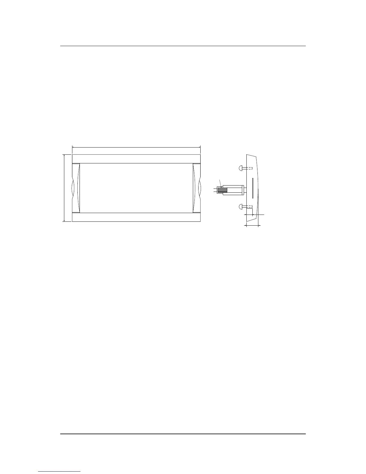
Display, AOP-1 and AOP-2 (see diagram below)
Panel door mounting:
0.7 Nm, 6.2 lb-in
Sub-D screw:
0.2 Nm, 1.8 lb-in
DC-DC converter terminals:
0.5 Nm, 4.4 lb-in
220.0 (8.661)
115.0 (4.528)
Display
20.0 (0.787)
0.7 Nm
Screw M3
Bossard BN5687
or similar
0.2 Nm
9P Female
Sub 0
connector
Max. 10 mm
Min. 6 mm
ML-2 installation instructions 4189340582
UK
Mounting and dimensions
DEIF A/S
Page 10 of 64
9
11
Table of Contents
Default Chapter
2
Table of Contents
2
1 Delimitation
4
Scope of Installation Instructions
4
GPC-3, GPU-3 and PPU-3
4
ML-2 Installation Instructions
4
2 General Information
5
Warnings, Legal Information and Safety
5
Warnings and Notes
5
Legal Information and Disclaimer
5
Safety Issues
5
Electrostatic Discharge Awareness
5
Factory Settings
5
About the Installation Instructions
6
General Purpose
6
Intended Users
6
Contents and Overall Structure
6
3 Mounting and Dimensions
7
Mounting of the Unit
7
Unit Dimensions
7
Panel Cutout
8
Drilling Template
9
Mounting Instructions
9
Tightening Torques
10
4 Hardware
11
General Hardware Description
11
Board Slot Positions
11
Unit Topside Overview
12
5 I/O Lists
13
I/O List and Terminal Strip Description - GPU, GPU Hydro
13
Slot #1, Power Supply and Binary I/O
13
Slot #2, External Communication (Optional)
14
Slot #3, Digital I/Os (Option M12)
16
Slot #4, GOV/AVR (Optional)
17
Slot #5, AC Measuring
20
Slot #6, I/O Extension (Optional)
20
Slot #7, Engine Interface Board (Option M4)
22
Slot #8, Communication and I/O (Optional)
23
Digital Inputs
24
Relay Outputs
25
I/O List and Terminal Strip Description - GPC, PPU
26
Slot #1, Power Supply and Binary I/O
26
Slot #2, External Communication (Optional)
27
Slot #3, Digital I/Os
29
Slot #4, GOV/AVR
30
Slot #5, AC Measuring
33
Slot #6, I/O Extension (Optional)
33
Slot #7, Engine Interface Board (Option M4)
35
Slot #8, Communication and I/O (Optional)
36
Digital Inputs
38
Relay Outputs
39
6 Wirings
40
AC Connections
40
3-Phase
40
3-Phase, 2-Phase Voltage, 1-Phase Current
41
1-Phase
42
2-Phase
43
CAN Bus Load Sharing (Option G9)
44
Modbus, RS-485 (Option H2)
44
Modbus, RS-232 (Option H9.2)
46
Profibus DP (Option H3)
47
CAN Bus Engine Communication (Option H5)
48
CAN Bus Engine Communication (Option H7)
49
Display Cable (Option J)
50
Load Sharing Lines (Option G3)
50
Mechanical Speed Governor
51
AVR with Relay Outputs
51
Electronic Speed Governor
52
AVR with Analogue Outputs
52
Digital Inputs
53
Digital Inputs with Wire Break Supervision (Option M4)
53
Multi-Functional Inputs (Option M4)
54
Magnetic Pickup (MPU) Input (Option M4)
55
Analogue Inputs (Option M15.X)
56
Stop Coil with Wire Break Detection (Option M4)
56
Transistor Outputs
56
Additional Display Unit, DU-2 (Option X2)
58
Additional Operator's Panel, AOP-1 (Option X3)
59
Additional Operator's Panel, AOP-2 (Option X4)
59
7 Technical Information
61
Technical Specifications
61
Other manuals for Deif GPU-3 Hydro
Quick Start Guide
23 pages
General Guidelines For Commissioning
25 pages
5
Based on 1 rating
Ask a question
Give review
Questions and Answers:
Need help?
Do you have a question about the Deif GPU-3 Hydro and is the answer not in the manual?
Ask a question
Deif GPU-3 Hydro Specifications
General
Brand
Deif
Model
GPU-3 Hydro
Category
Controller
Language
English
Related product manuals
Deif GPC-3
29 pages
Deif GC-1F
11 pages
Deif AGC-4
26 pages
Deif AGC-3
65 pages
Deif SGC 120
76 pages
Deif CGC 400
14 pages
Deif AGC 150
38 pages
Deif SGC 420
86 pages
Deif CGC 200
43 pages
Deif PPU 300
130 pages
Deif AGC-4 Mk II
50 pages
Deif Multi-line 2
170 pages