EasyManuals Logo

Deif GPU-3 Hydro Installation Instructions

Deif GPU-3 Hydro
64 pages
To Next Page IconTo Next Page
To Previous Page IconTo Previous Page
Page #51 background imageLoading...
Page #51 background image
6.1.13 Mechanical speed governor
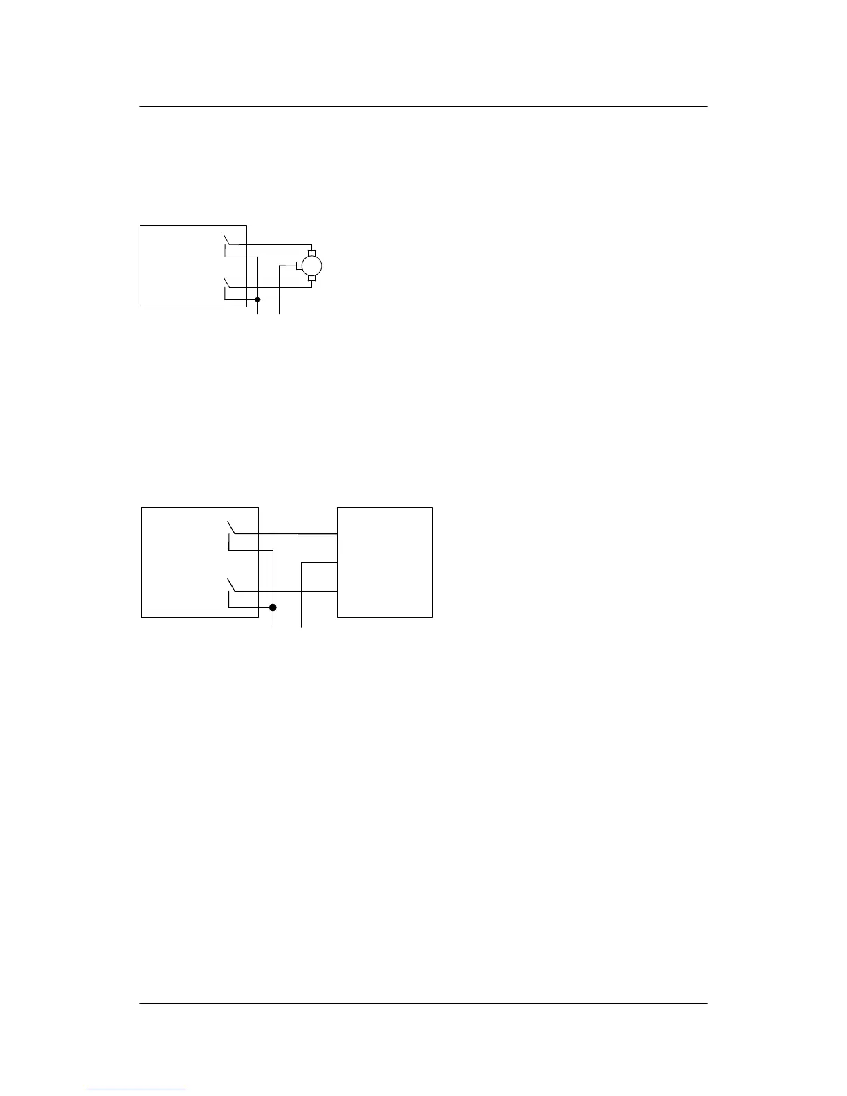
The illustration below shows the necessary connections to carry out speed control using relay outputs.
Multi-line 2
Speed lower
Speed raise
Ø
68
67
66
65
Supply for
Pilot motor
Ø
Pilot
motor
Lower
speed
Raise
speed
In order to extend the lifetime of the internal relays and prevent unwanted switching noise, it is recommended
to use free wheel diodes (1N4007), if a DC voltage is used for the regulation. If an AC voltage is used for the
regulation, it is recommended to use a varistor. The diode/varistor must be placed across the terminals of the
pilot motor/external regulation relay coil.
6.1.14 AVR with relay outputs
Multi-line 2
Voltage lower
Voltage raise
Ø
71
72
69
70
Supply for
AVR voltage
control
Ø
Common
Lower Voltage
Raise Voltage
AVR
ML-2 installation instructions 4189340582
UK
Wirings
DEIF A/S Page 51 of 64

Table of Contents

Other manuals for Deif GPU-3 Hydro

Questions and Answers:

Question and Answer IconNeed help?

Do you have a question about the Deif GPU-3 Hydro and is the answer not in the manual?

Deif GPU-3 Hydro Specifications

General IconGeneral
BrandDeif
ModelGPU-3 Hydro
CategoryController
LanguageEnglish

Related product manuals