5.2 I/O list and terminal strip description - GPC, PPU
5.2.1 Slot #1, power supply and binary I/O
For the relay outputs, the following terms will be used:
NO means Normally Open
NC means Normally Closed
Com. means common terminal for the relay in question
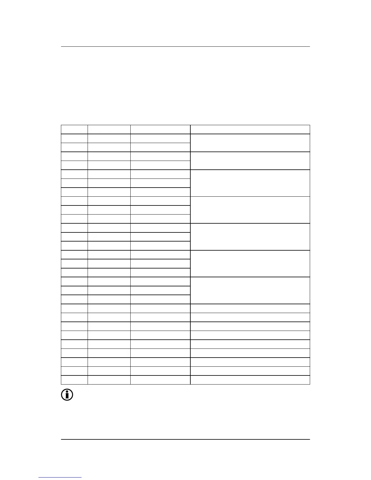
Terminal Function Technical data Description
1 +12/24 V DC 8 to 36 V DC Power supply
2 0 V DC
3 NC Status relay Normally closed relay, processor/power supply
status supervision
4 Com. 24 V/1 A
5 NO Relay 5 Alarm horn/configurable
6 Com. 250 V AC/8 A
7 NC
8 NO Relay 8 Configurable
9 Com. 250 V AC/8 A
10 NC
11 NO Relay 11 Configurable
12 Com. 250 V AC/8 A
13 NC
14 NO Relay 14 Open GB
15 Com. 250 V AC/8 A
16 NC
17 NO Relay 17 Close GB
18 Com. 250 V AC/8 A
19 NC
20 Open collector 1 Transistor out (relay 20) Configurable as standard relay output
21 Open collector 2 Transistor out (relay 21) Configurable as standard relay output
22 Com. Common Common terminal for terminals 20 and 21
23 Digital input Optocoupler Alarm inhibit 1/configurable
24 Digital input Optocoupler Remote alarm acknowledge/configurable
25 Digital input Optocoupler Start sync./control/configurable
26 Digital input Optocoupler GB open
27 Digital input Optocoupler GB closed
28 Com. Common Common for terminals 23-27
The power supply must be protected with a 2 A slow-blow fuse.
ML-2 installation instructions 4189340582
UK
I/O lists
DEIF A/S Page 26 of 64