EasyManua.ls Logo

Deif GPU-3 Hydro - Additional Display Unit, DU-2 (Option X2)

Deif GPU-3 Hydro
64 pages
To Next Page IconTo Next Page
To Previous Page IconTo Previous Page
Loading...
6.1.24 Additional display unit, DU-2 (option X2)
Standard display DU-2 Additional standard display DU-2
OFF
ON
App./Bootl.
End Res.
CAN 1
AOP-1
CAN 2
ML - 2
Red
Red/white
Terminal block
OFF
ON
App./Bootl.
End Res.
CAN 1 CAN 2
Red
Red/white
DIN Rail
5V DC
24V DC
+
-
+
-
Black
Black/White
1
2
1
2
Cable shield
Brown/white
Brown/white
6 - Black: GND
5 - Black/White: +5 VDC
4 - Brown: Not used
3 - Red: CAN L
2 - Brown/white: CAN GND
1 - Red/white: CAN H
6 - Not used
5 - Not used
4 - Not used
3 - Red: CAN L
2 - Brown/white: CAN GND
1 - Red/white: CAN H
Left CAN port (CAN 1) Right CAN port (CAN 2)
1...6 1...6
End resistor:
2 units connected: Dip switch no. 1 has to be set to ON on both units.
3 units connected: Dip switch no. 1 has to be set to ON on unit 1 and unit 3.
The maximum length of the CAN bus line is 200 m.
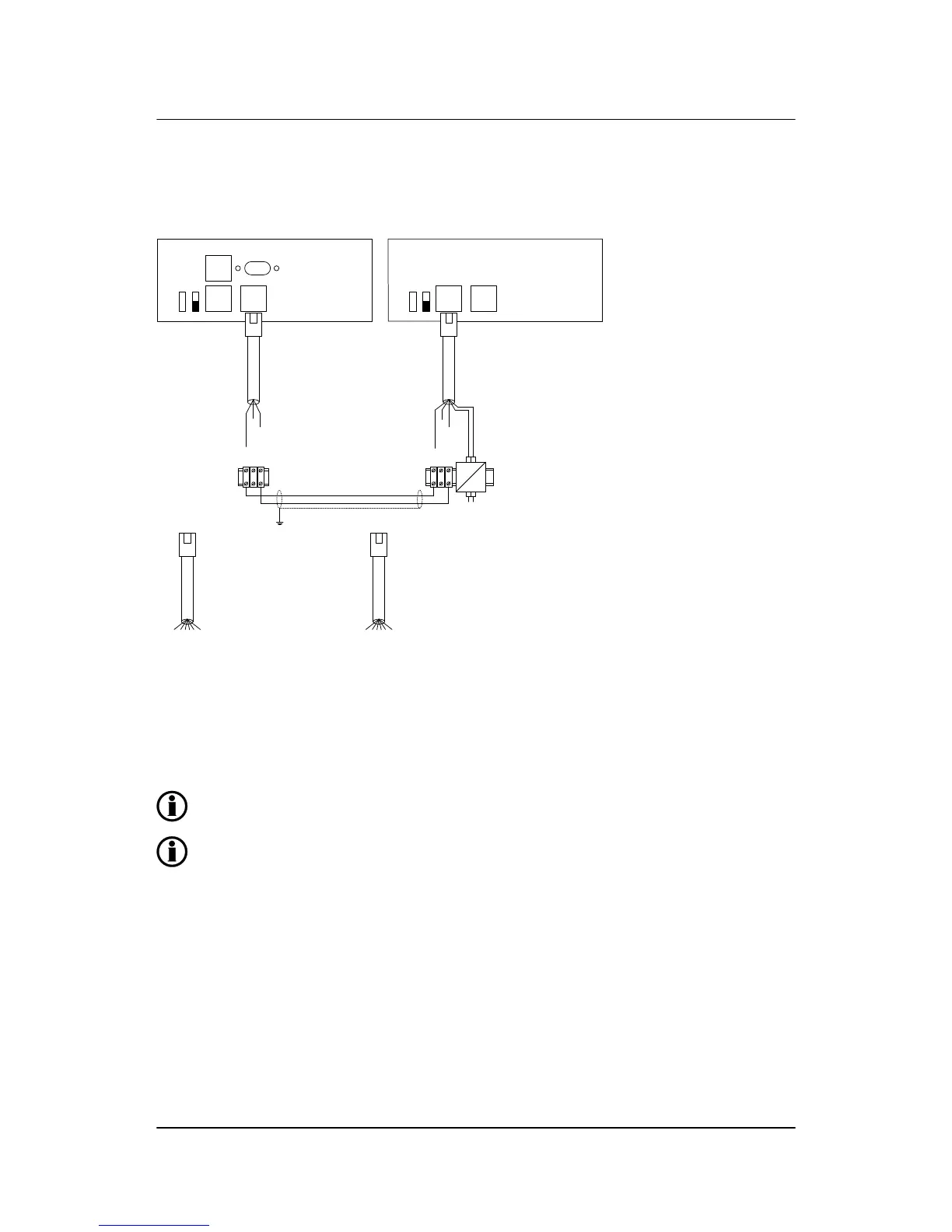
A DC/DC converter for the DC supply voltage and 2 × 1 m cable with an RJ45 plug in one end
and stripped wires in the other end are included in the DU-2 (option X2) delivery.
ML-2 installation instructions 4189340582
UK
Wirings
DEIF A/S Page 58 of 64

Table of Contents

Other manuals for Deif GPU-3 Hydro

Related product manuals