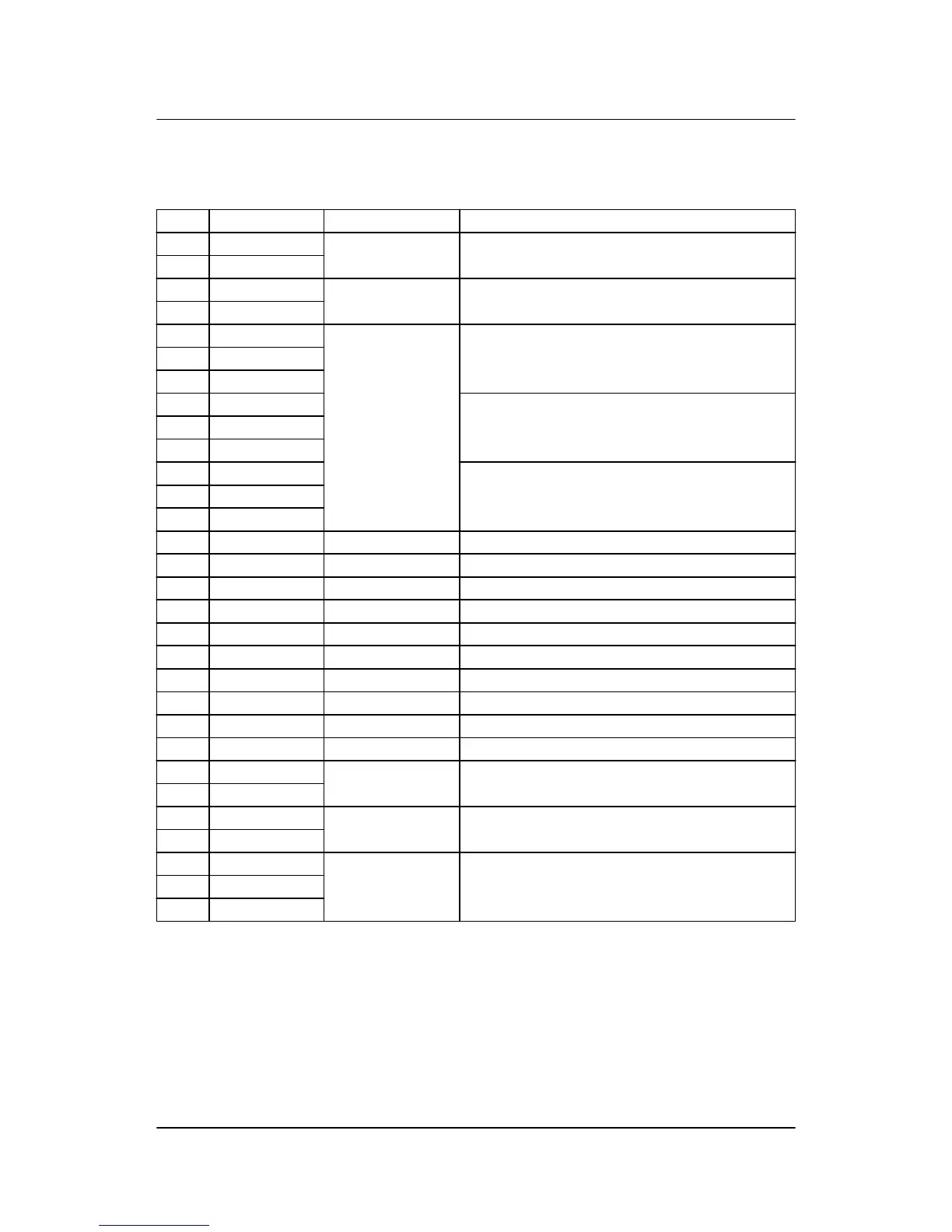
5.2.7 Slot #7, engine interface board (option M4)
Term. Function Technical data Description/preconfiguration
98 +12/24 V DC 8 to 36 V DC DC power supply
99 0 V DC
100 MPU input 0.5 to 70 V AC/
10 to 10000 Hz
Magnetic pickup (RPM)
101 MPU GND
102 A 0(4) to 20 mA
Digital w/wire break
Pt100
Pt1000
RMI
0 to 40 V DC
Multi-input 1
Preselected to digital input with wire break detection
103 B
104 C
105 A Multi-input 2
Preselected to digital input with wire break detection
106 B
107 C
108 A Multi-input 3
Preselected to digital input with wire break detection
109 B
110 C
111 Com. Common Common for terminals 112 to 117
112 Digital input 112 Optocoupler Configurable
113 Digital input 113 Optocoupler Configurable
114 Digital input 114 Optocoupler Shutdown override/configurable
115 Digital input 115 Optocoupler Configurable
116 Digital input 116 Optocoupler Running feedback/configurable
117 Digital input 117 Optocoupler Configurable
118 Digital input 118 Optocoupler Emergency stop and common for 119 and 120
119 NO Relay 24 V DC/5 A Run coil/configurable
120 NO Relay 24 V DC/5 A Start prepare/configurable
121 Com. Relay 24 V DC/5 A Crank (starter)/configurable
122 NO
123 Com. Relay 24 V DC/5 A Stop coil w/wire break/configurable
124 NO
A1 CAN-H CAN bus CAN bus J1939 engine interface (option H7)
A2 CAN GND
A3 CAN-L
ML-2 installation instructions 4189340582
UK
I/O lists
DEIF A/S Page 35 of 64