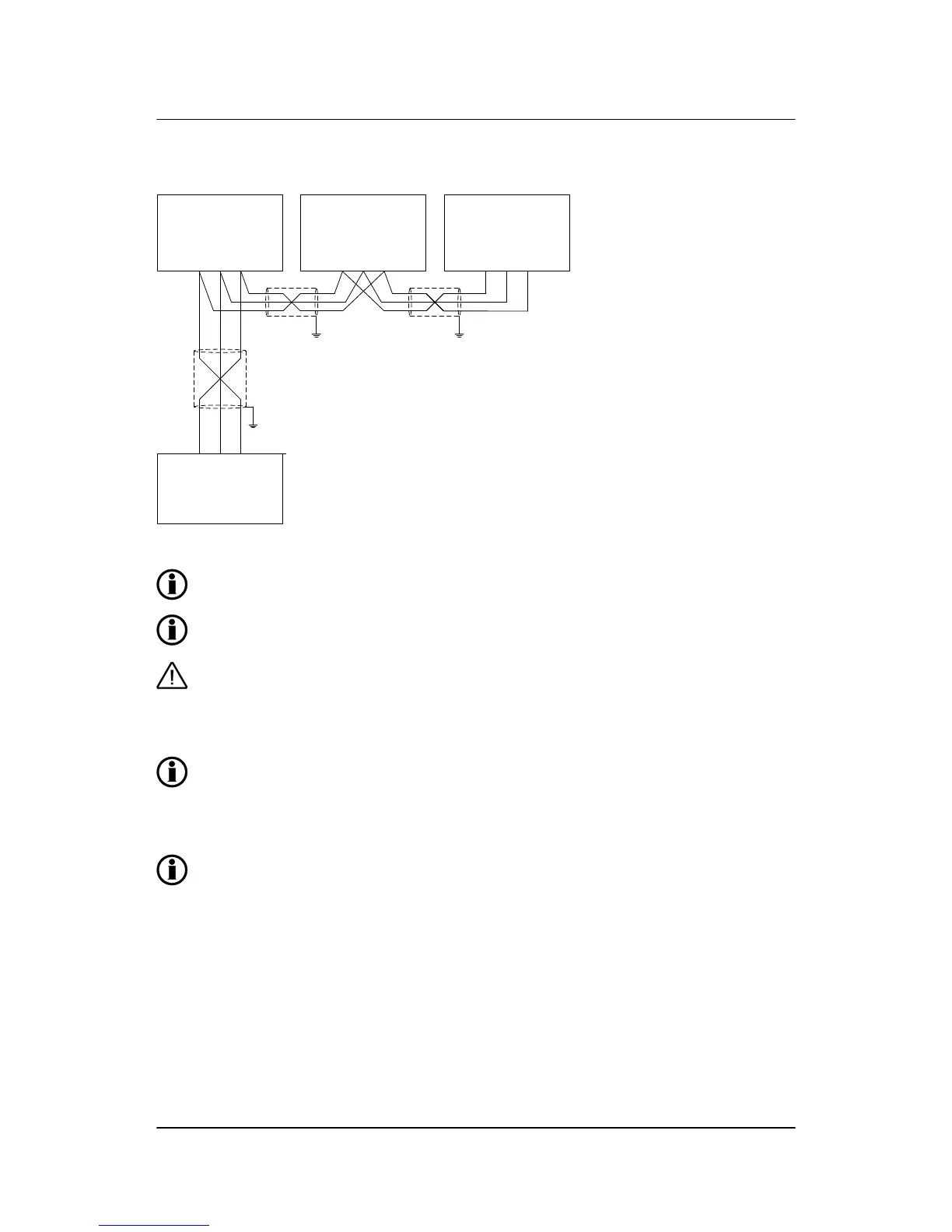
Connect shield to ground at one end only. Shield ends must be insulated with tape or insula-
tion tubing.
Use shielded twisted cable.
This solution is only feasible if the COM line is insulated. Check PLC/other device before con-
necting. A non-insulated COM line may result in damage to the equipment.
Normally, the Modbus does not need bias resistors (end terminators). These are only needed
in case of very long lines and/or many nodes (>32) on the Modbus network. If bias resistors
are needed, the calculation should be based on the following data:
● A line internal pull-up bias resistor: 22 kΩ
● B line internal pull-down bias resistor: 22 kΩ
● Receiver input sensitivity: +/-200 mV
● Receiver input impedance: 12 kΩ
Cable: Belden 3105 A or equivalent. 22 AWG (0.6 mm
2
) twisted pair, shielded, <40 mΩ/m, min.
95 % shield coverage.
ML-2 installation instructions 4189340582
UK
Wirings
DEIF A/S Page 45 of 64