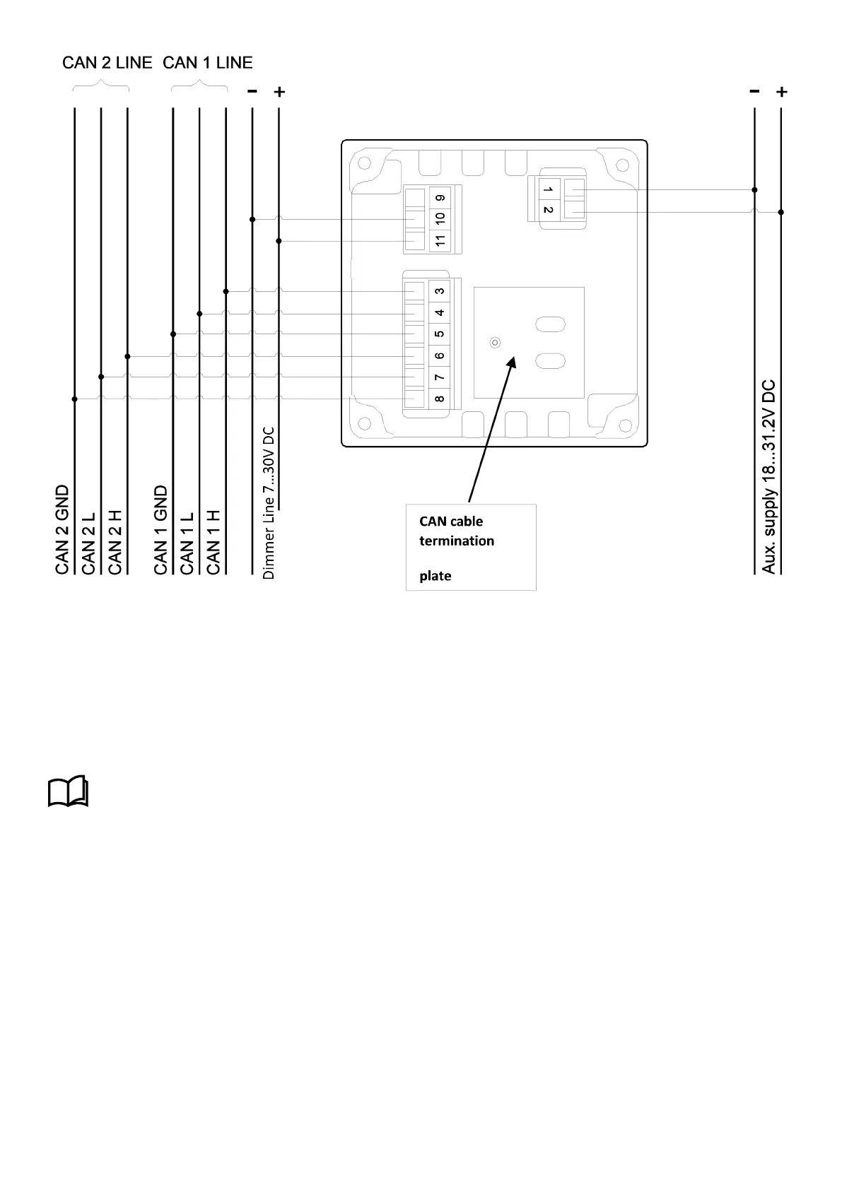
NOTE The plate shown at the arrow is for fastening the CAN cables with two strips. The strips are not included. Keep the
isolation on the cables, so the screens are not mutually connected.
CAN ground
In general, CAN 1 GND and CAN 2 GND should not be connected. In case of noisy environments the cable screen from CAN
cable 1 and 2 can be connected to input CAN 1 GND and to input CAN 2 GND on the indicator respectively.
NOTE
It is recommended that the two cable screens for CAN 1 and CAN 2 are not connected.
More information
See Commissioning for more information about terminating the CANopen line.
NOTE Remember to terminate both ends of the CANopen line with a 120 Ohm resistor.
2.1.5 Dimmer setup for dual CANopen indicators
The illumination can be controlled from the CANopen line or by the dimmer line on terminals 10 and 11.
To be able to control the illumination over the full range by means of the CANopen line, it is important that the voltage level
on terminals 10 and 11 is approximately 24 V. This can be accomplished simply by connecting terminal 10 to terminal 1 and
terminal 11 to terminal 2 using the aux. supply voltage as voltage input for the illumination.
If the illumination is controlled from the dimmer line, the CANopen parameter for illumination must be set to 100 % (factory
setting). Because the two systems influence each other, it is possible to adjust the illumination from both sources at the
same time.
Installation and commissioning guide 4189350024O EN
Page 11 of 39

 Loading...

