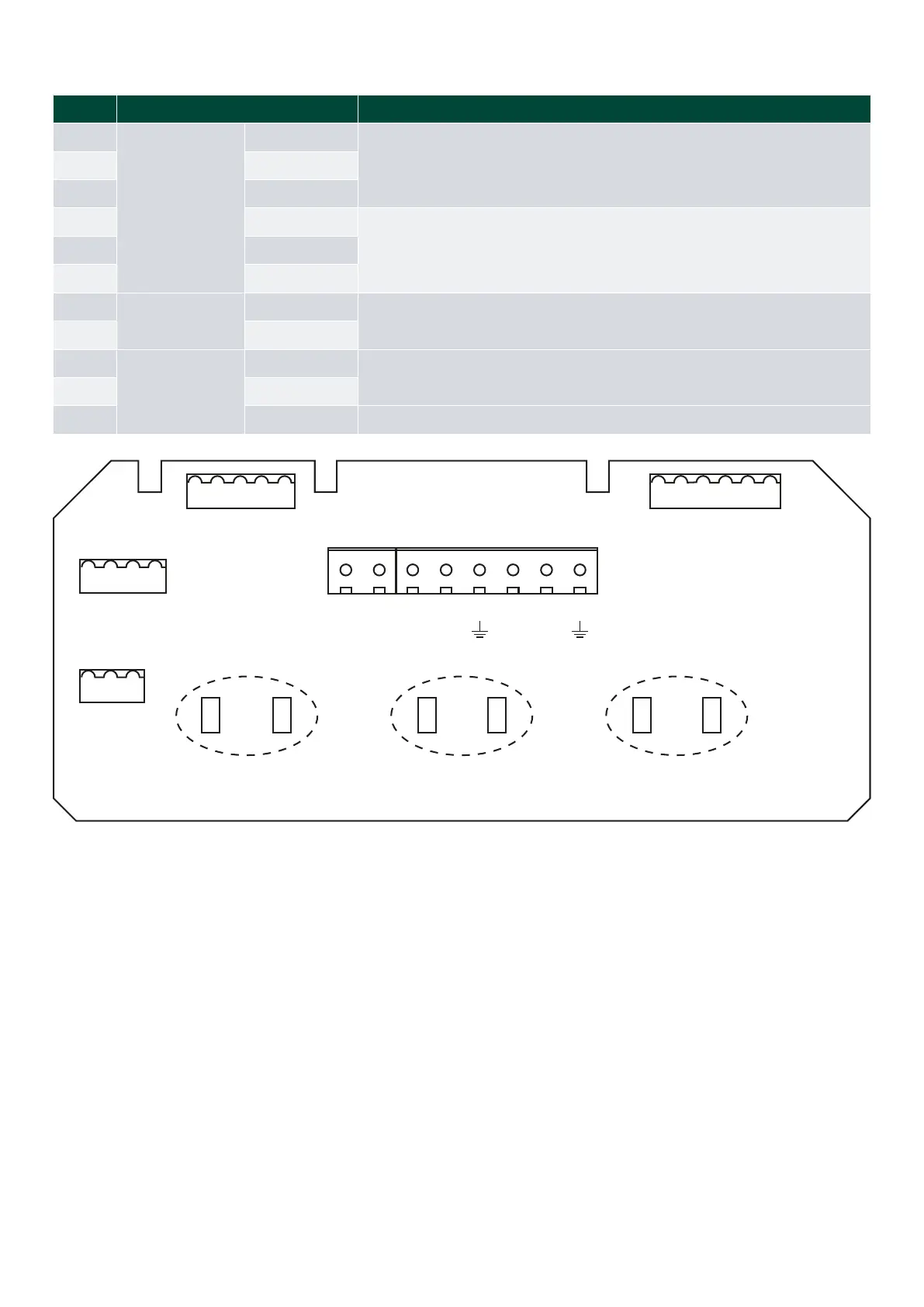
4.1.3 CANopen input terminal connections
Pin no. Function Note
GND
CAN connection
CAN 1 GND
CAN 2 line/or for external switch for calibrating sCAN (see user manual)
L input CAN 2 L input
H input CAN 2 H input
GND CAN 1 GND
CAN 1 line (sCAN line) L input CAN 1 L input
H input CAN 1 H input
24 V
Supply voltage
24 V DC
0 V 0 V DC
9
X4 connector
Illumination
Orange wire
Dimmer potentiometer kOhm)
10 Brown wire
11 Red wire Wiper on the dimmer potentiometer
X5
X3
X1
CAN 1
CAN 2
CAN 1 CAN 2
X6
X4
9 11 10
83 81 93 91
0 V
24 V
H INPUT
L INPUT
GND
H INPUT
L INPUT
GND
- +
NOTE Use strips to terminate cable shields to PCB to avoid noise (see the dashed circles).
NOTE Jumpers J1 and J2 are used as end resistors (terminations) of CAN 1 and CAN 2. shown on image.)
4.1.4 Dimmer wiring
The can be ordered with a built-in dimmer on the front plate for without a built-in dimmer.
Installation and commissioning guide 4189350024O EN
Page 21 of 39

 Loading...

