5.3.1 Start setup mode
The normally unused CAN 2 line is used as a set-up selector. The “CAN (terminal must be connected to “CAN 2
GND” (terminal via an external switch and through a 10 k resistor.
When the switch is closed, the indicator is put into set-up mode and the time the switch is closed is used to select the
different settings. The time the switch is opened again is used to select and store new values.
Protection of setup:
• Setup switch/input must not be “closed” the first 30 seconds after power-up. If it is “closed”, the calibration function will
be inhibited until new power-up without “closed” calibration input.
• Calibration will not react to any input “Close” < 5 seconds (closed 5 seconds without any interruption).
• If the input is “closed” for seconds, the calibration sequence is terminated without storing any change and a new
sequence can first be started after an input “open” for at least 5 seconds.
The above should prevent an accidental short-circuit either a short glitch (a wire hitting the terminal) or continuous short-
circuit to change any setting.
NOTE
A power loss during setup can cause an incorrect setup. If power is lost during setup the process must be
restarted.
5.3.2 Synchronise XL indicators over CAN
XL indicators using the same (that is listening for data coming from this CAN will automatically be synchronised
with the XL where the set-up process is performed.
5.3.3
Replacing indicators in a calibrated system
When an indicator is replaced in a calibrated system, the system has to be recalibrated.
5.3.4
Setup indicators without 360° scales
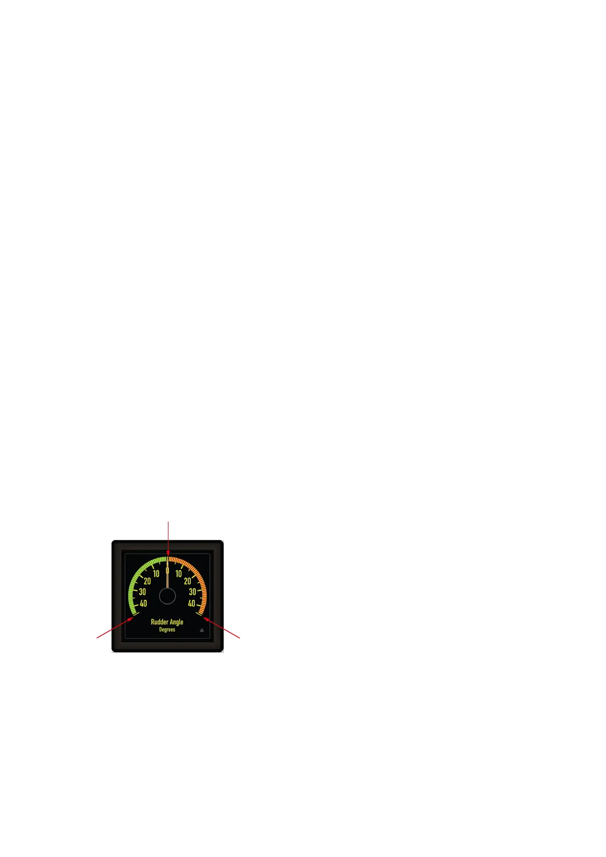
The indicator scale can be divided into two sections, minimum to zero and zero to maximum.
Zero scale value
Minimum scale
value
Maximum scale
value
Set zero position
The sensor/input must be positioned at desired zero value and on the indicator, the set-up switch must be closed:
• After 5 seconds, the indicator pointer will move to 0 degree (just check, no action).
• Between 5 and 10 seconds, the new zero scale value is stored when set-up switch is opened (the LED will flash once for
verification).
NOTE
When controlled by a processor, a switch close time of 5.5 to 9.5 sec must be used.
Installation and commissioning guide 4189350024O EN Page 29 of 39

 Loading...

