3. BW wiring and installation
3.1 Wiring
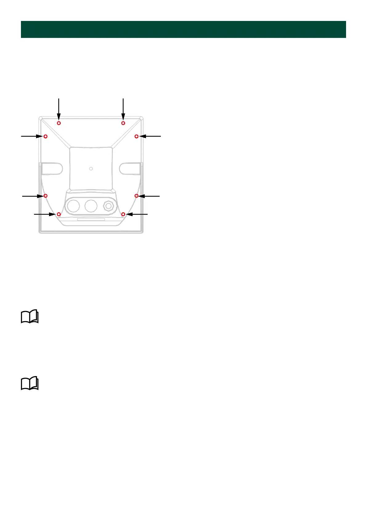
To access the terminals, the bulkhead box must be removed by unscrewing the eight screws located on the rear side of the
box. To reach the screws, use a torx T10 tool with a long bit mm).
Location of the rear screws on BW144
NOTE BW192 also has eight screws.
Having unscrewed the bulkhead box, the indicator can be taken out of the box. The wiring of the BW terminals is identical
to the description for XL instruments.
When the wiring is done, the indicator is remounted in the bulkhead box using the eight screws. Recommended torque for
the screws is 0.8 Nm The included (black) gasket/frame is mounted in the groove on the indicator frame with the
rubber rim side into the groove.
More information
See XL wiring and installation, Wiring for the wiring diagrams that can be used for BW.
3.1.1 Dimmer wiring
In addition to the PG glands, the bulkhead box is equipped with a potentiometer. This potentiometer is used for local
dimmer for the indicator.
More information
See XL wiring and installation, Wiring for more information about how to wire the dimmer potentiometer.
3.1.2 Cable glands
The bulkhead box is equipped with two PG cable glands:
• PG9 (cable gauge: mm)
• PG16 (cable gauge: mm)
On delivery from DEIF, the two PG glands are sealed with protection blind plugs.
Installation and commissioning guide 4189350024O EN
Page 17 of 39

 Loading...

