NOTE Only one instrument can be connected in the current loops.
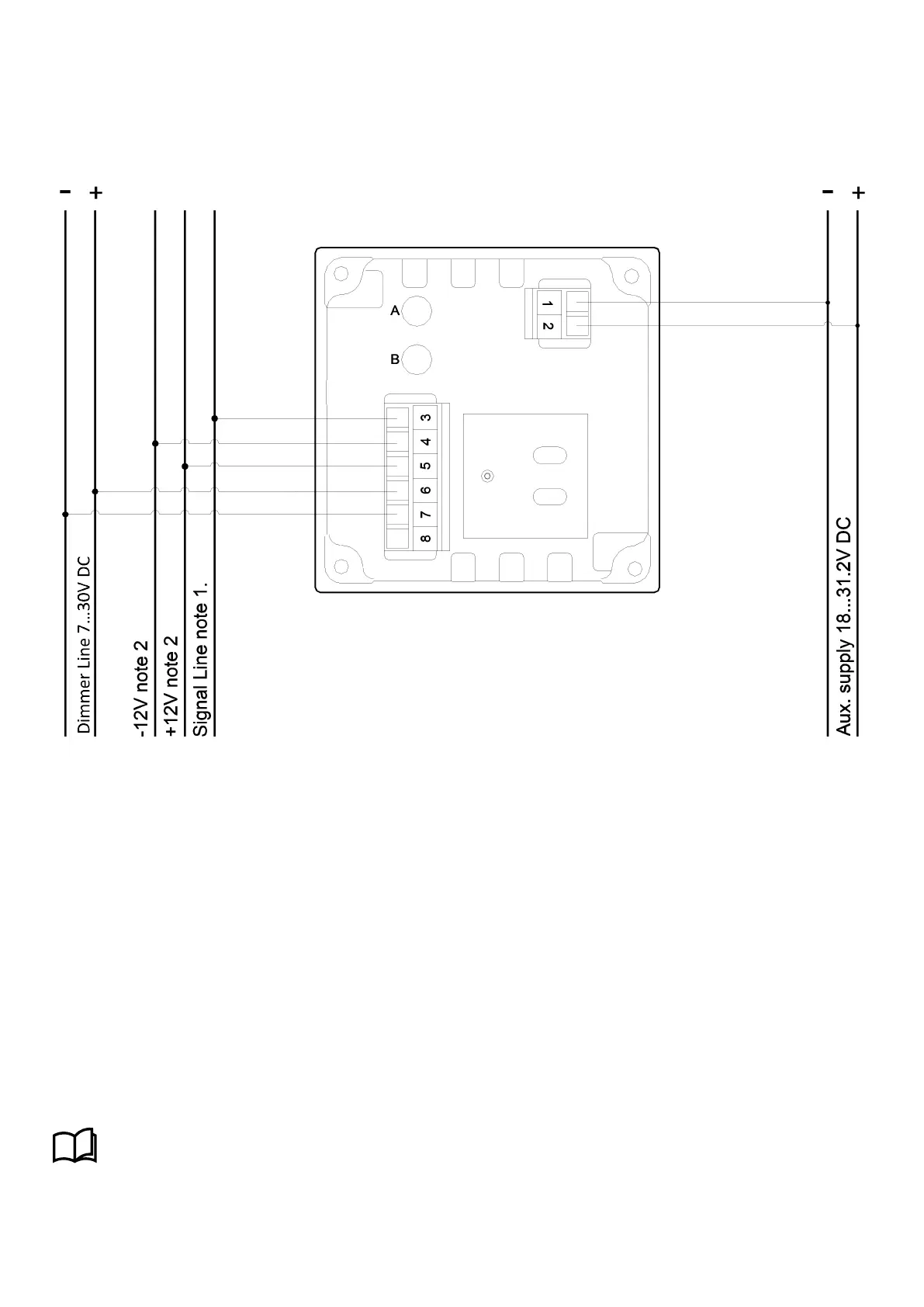
2.1.2 Rudder potentiometer analogue indicator
Special input for direct connection to rudder potentiometer. Be aware that this is not standard functionality.
Note that:
1. The signal line is identical to the signal on the rudder potentiometer wiper.
2. The and V DC V can be the same voltage as the aux. voltage.
As standard the aux. voltage can be between 18…31 Vdc. In cases where the aux. voltage is used for the V and V,
this voltage must be stabilised and not higher than 25 V, and the same voltage must be used for supplying the rudder
potentiometer itself.
Adjustment
The min. potentiometer can be used to correct the zero position; e.g. if the rudder is located in centre position then
the reading on the indicator can be corrected to indicate 0°.
The max. potentiometer can be used to correct the max. position; if the rudder is turned to max. port side or starboard
side, then adjust by means of the potentiometer marked A until correct reading on the scale. The max. potentiometer has an
extended adjustment range in the above version; the span can be adjusted to cover V to V.
More information
See Commissioning for more information about adjusting standard analogue input indicators.
Installation and commissioning guide 4189350024O EN Page 9 of 39

 Loading...

