7. Appendix Pointer positions based on input
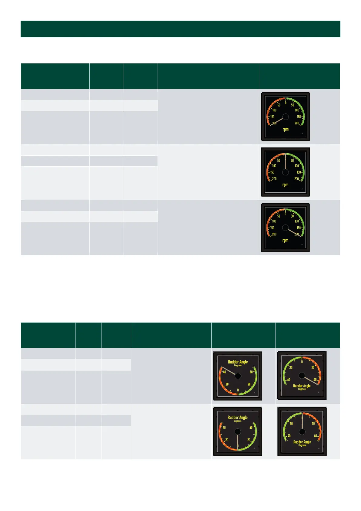
7.1 Standard analogue indicators
Input type Input 1 Input 2 Pointer position (scale)
STD design:
EM=12
Pointer CW
4 to 20 mA 4 mA -
0 to 10 V
0 V -
to 0 to 10 V V -
4 to 20 mA 12 mA -
0
0 to 10 V
5 V -
to 0 to 10 V 0 V -
4 to 20 mA 20 mA -
0 to 10 V
10 V -
to 0 to 10 V 10 V -
7.2 Rudder indicators
When used in a system with XL must be CCW, or must be 20 to 4 mA and XL CW.
XL 4 to 20 mA can be changed from CW to CCW by the customer, and can also be changed from CW to CCW during
installation.
Input type
Input 1 Input 2: Pointer position (scale)
FWD design:
EM=6
Pointer CCW1
AFT design:
EM=12
Pointer CCW*
4 to 20 mA - 4 mA
0 to 10 V
0 V -
to 0 to 10 V V -
4 to 20 mA - 12 mA
0
0 to 10 V
5 V -
to 0 to 10 V 0 V -
Installation and commissioning guide 4189350024O EN Page 36 of 39

 Loading...

