scale by means of B (zero), then turn the rudder to give an input close to maximum and adjust the reading by means of A
(max.).
NOTE It is not recommended to perform the minimum and the maximum adjustment with an input signal corresponding
exactly to min. and max. input. For example, if the input signal is 0 V when adjusting a 0 to 10 V instrument. The
potentiometer named B will not give any adjustment below the corresponding zero point on the scale, and there is
a risk of adding an unwanted offset causing a linearity error over the whole scale. Similarly for the maximum
adjustment.
NOTE Minimum adjustment must be performed before maximum adjustment.
5.2.3 Adjustment functionality
XL type Potentiometer A Potentiometer B
240 degree
pointer
Maximum (or gain) adjustment
Range: Approx. % of full scale
Only use this when the pointer is in maximum
position
Zero (or minimum) adjustment
Range: Approx. % of full scale
Use this for zero correction in minimum or
midpoint position
360 degree
pointer
At full CW, the EM (electrical middle) is as standard.
At full CCW, the EM changes to degrees of
standard.
degree digital offset of the pointer/disc.
Similar to a mechanical adjustment on a moving
coil indicator.
The maximum position is fully CW on CW types and fully CCW on CCW types.
If you need to revert to factory settings on the adjustment, place the potentiometers in the middle position.
5.2.4
Out of range definition
When the input is more than 2 % outside the nominal range to 102 the pointer moves to “out-of-range” position.
More information
See Appendix A for examples of out of range pointer positions.
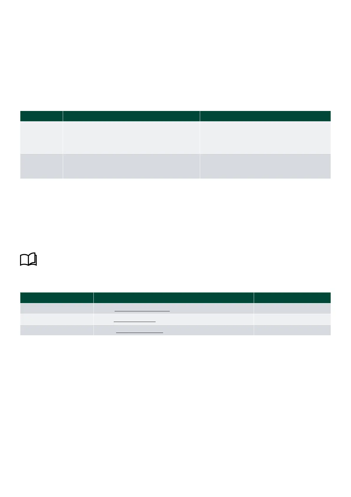
Examples of out of range values
Out of range (low)
Working range Out of range (high)
< 3.60 mA 3.60 to 4.00 to 12.00 to 20.00 to 20.40 mA > 20.40 mA
< V to 0.0 to 5.0 to 10.0 to 10.2 V > 10.2 V
< V to to 0.0 to 10.0 to 10.2 V > 10.2 V
NOTE The 2 % value is calculated from the maximum input value.
5.3 Commissioning sCAN indicators
The XL and indicators are equipped with an amber LED indicator located in the corner of the scale.
After power-up, the LED is flashing once every second until a valid CAN signal is present. Then the LED turns off.
In the sCAN version, some basic setting can be performed on the system/indicators:
• Zero setting
• Minimum value setting
• Maximum value setting
• CW or CCW pointer movement selection
Installation and commissioning guide 4189350024O EN
Page 28 of 39

 Loading...

